Continue to Site

Welcome to our site!

Electro Tech is an online community (with over 170,000 members) who enjoy talking about and building electronic circuits, projects and gadgets. To participate you need to register. Registration is free. Click here to register now.

  • Welcome to our site! Electro Tech is an online community (with over 170,000 members) who enjoy talking about and building electronic circuits, projects and gadgets. To participate you need to register. Registration is free. Click here to register now.

Resistor Value?

Status
Not open for further replies.

jifcom

New Member
Hi all,
new here but unfortunately old elsewhere.
I have a quick question about a Resistor value?
to put in context I will explain, I am into vintage HiFi, all Yamaha gear from the 70s.

I just picked up a almost mint 1977 Yamaha CA-2010 Amp. for my collection, everything all working lovely bit no lamps working?
I have had to change quite a few bulbs before in my collection, not hard but gets a bit weary as it seems they blow quite regularly. I had though about LEDs but when looked into it, found it quiet daunting!!

so anyway, took the top off and removed the lamp board but a closer look did not see the tell tale burn on the lamps so carefully plugged back in and turned on, then tested the voltage across the power feeds to the board, Nothing!
so then turned off and unplugged and turned over the Amp to remove the bottom plate to access the fuses, but before I could test them I noticed a rather blackened resistor!
and the fused had blown as well.

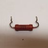
Unable to see what the value was of the resistor was, I referred to the wiring diagrams for the Amp, found out its a 10 ohm resistor but thats all I know, so no idea what wattage?
I have attached a screenshot of the diagram and the resistor highlighted in Yellow.

Can anyone identify the resistor? in context to the diagram, take into account that its more than 40yrs old, what would be the modern equivalent?
before anyone ask's, the photo of the resistor is not the one blown, I took it out of another identical Amp.

Any help would be appreciated by this Oldie, who need to play music loud to be able to hear it (or thats what I tell the wife :) )

Regards
Jon
 

Attachments

  • 20190813_214342.jpg
    20190813_214342.jpg
    170.2 KB · Views: 146
  • Power board.jpg
    Power board.jpg
    136.8 KB · Views: 125
Welcome to ETO.

There are five lamps, each rated at 60mA, so the total load will be 300mA after the initial switch on surge.

300mA through a 10 Ohm resistor will dissipate 0.3 x 0.3 x 10 = 0.9 watts
So a 1 watt resistor would be adequate.

However, for good reliability it is better to run components at no more than half their power rating, so it would be better to use a 2 or 3 watt resistor as a replacement.

Also consider that someone may have installed lamps with a higher current rating, that would cause burning of the existing resistor.

JimB
 
Agree on 2W, but why did it burn and the fuse blow? Check carefully for any shorts in the lamp wiring, and be sure the installed lamps are the correct ones.
 
I'd say it was around 2 watts as well, however the one you pic'd looks Ok to me, are to you able to meter it and see what it reads?
 
The schematic shows '2P' for that resistor: another indication it's a 2Watt one.
 
Last edited:
Thank you all for your comments, especially JimB for a easy to understand comment, 10 ohm 2w wirewound resistor now ordered.
thank you also to the others who confirmed the resistor size and to commented on other things to check.

I checked the bulbs on the lamp assembly, they are not like the other I have for spares which I know are 12v 60mA but unknown value as nothing written on the bulbs, so that could be the problem? after installing the correct bulbs, I checked with meter all the way back to lamp board and all is fine, will double check again after fitting new resistor when it arrives.

The photo was of a good resistor I took out of another fully working CA-2010 just to take the photo. Sorry brain fade, hadn't thought of testing with a meter!
Lot to learn and remember, I am teaching myself electronics as now retired and would like to maintain my HiFi as much as possible to save money on sending to a Tech. in the meantime until I am confident on work on them, anything I'm not sure of I will no doubt ask on here and if Ness. will send to the Tech.

Thank you all again.
I will be back :cool:
Jon
 
Back in my days of audio repairs we used to have a draw full of dial lamps - there was an incredible range of different styles, voltages, and currents - and fitting too high a current bulbs could easily have burnt the resistor up in the past. Another common problem was the wrong bulbs getting too hot, and melting the dial or surrounding plastic.

Assuming the original wasn't a wirewound, it was quite common for such resistors to go lower in value, due to the heat they dissipated, in turn this made them get hotter, which made them go lower still - eventually the resistor destroys itself.
 
0.9 watts
So a 1 watt resistor would be adequate.
Looked at Vishay 2W resistors. At 100% and 25C room temp the resistor inside temperature = 275C.
In the box the air temperature is hotter than "room temp".
You probably don't want a part running hot enough to take the skin off your finger. (or milt solder)
50% power 25C room = 150C resistor
 
You probably don't want a part running hot enough to take the skin off your finger. (or milt solder)

There's nothing worse than your solder 'milting' :D

Running a resistor anywhere near it's specification is a REALLY bad idea, but regardless, no matter the size of the resistor it's still dissipating 0.9W and is likely to run pretty hot. It's normal to find the PCB discoloured where such resistors are mounted (and usually mounted spaced well off the board), and the copper tracks deformed and difficult to solder to any more.
 
When parts burn out I think they were under engineered so I like to replace them with over kill to play it safe. I would use a 3W resistor with a heat sink or 5W resistor with no heat sink. Either way test them to see how hot the replacement resistor gets.
 
I'm wondering if you want some help to try to convert the illumination to LED's?

One thing that comes immediately to mind is to put a very small universal power supply 100-285 vac to say 24 VDC and go from there.

These https://us.idec.com/Catalog/Product...STD-2S&FamilyName=Family&SeriesName=HW_Series are not bad lamps and they come in various voltages and colors and will work on AC as well.

The pilot lamp looks like a standard LED, so you can make that use any voltage.

It might not be cheap, but you would not have to do it again. The LEDs just get dimmer over time rather than burn out.

I did one conversion of a stereo indicator that wasn't straight-forward.
 
I'm wondering if you want some help to try to convert the illumination to LED's?
One thing that comes immediately to mind is to put a very small universal power supply 100-285 vac to say 24 VDC and go from there.
As there's already a 13VAC supply for the existing bulbs, if it were me I'd just stick a bridge rectifier on that, and perhaps a smoothing cap. The LEDs could be wired in series to reduce current demand.
 
Status
Not open for further replies.

Latest threads

New Articles From Microcontroller Tips

Back
Top