Continue to Site

Welcome to our site!

Electro Tech is an online community (with over 170,000 members) who enjoy talking about and building electronic circuits, projects and gadgets. To participate you need to register. Registration is free. Click here to register now.

  • Welcome to our site! Electro Tech is an online community (with over 170,000 members) who enjoy talking about and building electronic circuits, projects and gadgets. To participate you need to register. Registration is free. Click here to register now.

Resistor placement and wattage

Status
Not open for further replies.

thekenny

New Member
Hi everyone,
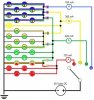
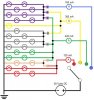
First up, I’m a complete newbie with electronics. I’ve had a 2-day class through the Army and done some reading, but have no practical experience. That said, I could use some help with my first project. Please forgive (and correct!) me if the diagram is done wrong… though I have had to color code it for my own sanity when soldering the wires and it is missing resistors per my question below.

I’m a UH-60 pilot and I’ve come across a demilitarized caution/advisory panel from the helicopter. I would like to display the lights associated with four scenarios. The lamps have a published spec of 28 volts DC and 40 mA nominal. I found that I can only run two in series before I get noticeable dimming, so I’ve wired the parallel branches to have a maximum of two lights each. I briefly tried a 12V power supply to see if I could tone it down a bit, but I could only get one in series to be bright, and with the number of lamps to light I didn’t want to draw that much current through 21 parallel circuit branches under the worst case scenario.

My question comes in on what resistors to use in the circuit and where to place them. I know by Ohm’s law, 28 V / .040 A = 700 Ω on each branch. Each light has a resistance of 50 Ω as measured on my multimeter, so that’s a 600 or 650 Ω resistor on each branch. Or, since there’s a rotary switch, would it be better to just do a single resistor immediately after the switch on each main branch, applicable to their maximum currents? For example, my “red” branch at 120 mA would need 233 Ω resistance. What is the best place to put them? Would that even work right?

Secondly, what kind of resistors would I need- specifically, wattage. I’ve seen .25 to 1 –watt resistors. With the formula V*V / R, I keep seeing that I need over 1 watt. On the above example of the “red” branch, 28V * 28V / 233Ω = 3.36 watts. Is this the correct method for determining my resistor requirement? If not, what type of calculation should I be making so I don’t set anything on fire?

I appreciate any help!
 

Attachments

  • cautionadvisory_schematic.jpg
    cautionadvisory_schematic.jpg
    43.8 KB · Views: 176
hi,:)

The resistance of the lamp when lit could be as much as 10 times the value you measure on the ohm meter when the lamp is 'cold'.

Ive looked a the dwg and I have read the notes,, but exactly what would you like to see happen as you rotate the select switch.?

EDIT: whats the marking on the lamps.? volts , watts etc.???
 
Last edited:
Basically, I'd like the switch to go through the process of showing the lamps that display when starting up the Black Hawk.

The Red node of the switch circuit should light a total of 6 lamps, 4 unique to the red wire off the switch and 2 that are also lit when the green switch position is selected.

The yellow position lights one unique light, 7 shared with the green switch, and 8 shared with both the green and blue.

The green position should light 4 unique lights, 8 shared with blue and yellow, 7 shared with just yellow, and 2 shared with red.

The blue position only lights 8 lights that are also shared with yellow and green.
 
What exactly you want to do? You want to light the lamps with the brightness that they are intended to have? Or you just want to simulate their current draw through a resistor?

We will proceed after you answer this.
 
Basically, I'd like the switch to go through the process of showing the lamps that display when starting up the Black Hawk.

The Red node of the switch circuit should light a total of 6 lamps, 4 unique to the red wire off the switch and 2 that are also lit when the green switch position is selected.

The yellow position lights one unique light, 7 shared with the green switch, and 8 shared with both the green and blue.

The green position should light 4 unique lights, 8 shared with blue and yellow, 7 shared with just yellow, and 2 shared with red.

The blue position only lights 8 lights that are also shared with yellow and green.

I follow, couple of questions .. are you using 12V lamps and a 24/28Vdc supply.?
 
Last edited:
The lamps are the ones that came with the panel itself. Looking at FEDLOG, the government's supply database, it lists the characteristics of the lamps themselves as 28 V DC and 0.040 A "nominal."

However, they will run at 12 V just as bright through pure experimentation, but only one will work in series with that voltage.

I'm using a 30 volt 1500 mA AC to DC power supply and a voltage regulator to bring it down to 28 volts.

Edit: the only marking I can find directly on the lamp is "CM327Q"
 
Last edited:
The lamps are the ones that came with the panel itself. Looking at FEDLOG, the government's supply database, it lists the characteristics of the lamps themselves as 28 V DC and 0.040 A "nominal."

However, they will run at 12 V just as bright through pure experimentation, but only one will work in series with that voltage.

I'm using a 30 volt 1500 mA AC to DC power supply and a voltage regulator to bring it down to 28 volts.

hi,

If you connect two 28V lamps in series and run from 28V they will be only 50%.

The sequence you will get with a dc supply will like this image.
 

Attachments

  • cautionadvisory_schematic.jpg
    cautionadvisory_schematic.jpg
    50.6 KB · Views: 153
Last edited:
Right, gotcha.

In this case, the 50% brightness is actually an acceptable level- I guess that's also why only one runs at half voltage at a good level

So I'll proceed from there and based on your question about simulating current draw, do I even need to use resistors then? If the lights are working bright enough while using half the voltage, and I assume (again newbie) they won't draw much more than their required (and measured) 40 mA, do I even really need to incorporate resistors into this circuit?

I can see wanting to use a 50Ω resistor on the two lines that only have one lamp in order to keep their brightness the same as the other branches, right?

hi,
If you want to run the single lamps themselves as 28 V DC and 0.040 A "nominal." lamps at the same brightness,
the resistor has to be 28/0.04 = 700R.!! Wattage = 14V * 0.04A = 0.56W say 1W min.

I would use a series 'hidden' lamp as the dropper resistor.:)

EDITED: Res value....
 
Last edited:
That makes pretty good sense to use hidden lamp as the resistor, since they're already rated at 1.12 watts. Might be hard to do since they're all attached to the panel, but I can always try some electrical tape inside the capsule holding the "hidden" lamp!

So there's no need for other resistors elsewhere if everything sort of self-regulates? That's a relief as playing with this higher voltage level was going to make me look for some hard to find components :)
 
from wiki

"For a supply voltage V,

Light output is approximately proportional to V^3.4
Power consumption is approximately proportional to V^1.6
Lifetime is approximately proportional to V^(−16)
Color temperature is approximately proportional to V^0.42 "

Your V-I relationship is hidden in the V^1.6 relationship.
P = VI=V^1.6, to get R solve for V/I at different I values (I does the filament heating).
Guaranteed this will scramble your brains every time you do it. I recommend using a spreadsheet to keep everything straight.
Define a K factor that changes with lamp rated wattage.
 
Last edited:
Status
Not open for further replies.

Latest threads

New Articles From Microcontroller Tips

Back
Top