Continue to Site

Welcome to our site!

Electro Tech is an online community (with over 170,000 members) who enjoy talking about and building electronic circuits, projects and gadgets. To participate you need to register. Registration is free. Click here to register now.

  • Welcome to our site! Electro Tech is an online community (with over 170,000 members) who enjoy talking about and building electronic circuits, projects and gadgets. To participate you need to register. Registration is free. Click here to register now.

Resistive Electronic Load

Status
Not open for further replies.

Quiet

New Member
Hi,
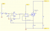
I am an MSc student in power electronics. I need an idea how to design an electronic load. The behaviour of the load should be "Resistive"; not constant current type or other. When voltage is increased I want current going throuh the load is increased as well. There is a pricipal circuit attached, i am not sure how precise it works. But i need other ideas as well.

Thanks in advance.
 

Attachments

  • resistive_load.gif
    resistive_load.gif
    118 KB · Views: 801
See the annotated schematic below. Note that, as the output voltage goes up, the current goes down. That's the wrong direction. You need a function with the form

Rout=Vout/Iout=k*Vctrl
Solving for Iout,
Iout=Vout/(k*Vctrl) or Iout=k'*Vout/Vctrl.

It looks to me like you need an analog divider, or perhaps a microcontroller, if you want DC current. If you can tolerate PWM, a microcontroller is still probably the easiest way to implement it.
If there is an easy way to do this in purely analog fashion, maybe one of the other guys here knows how to do it.
 

Attachments

  • resistive_load_anno.png
    resistive_load_anno.png
    445.2 KB · Views: 655
Hi,

Sounds to me like you want to make an artificial resistor,
presumably to provide loading conditions for a battery or some
power supply unit to test that the power supply works ok.

Presumably you want to be able to vary the resistance of it
to provide a heavy or a light load.

My own 'dummy loads' from years ago were made with simply a heavy
resistor of low ohms value in series with a power transistor, the
load being set by adjusting a small pot across base to collector.

This was very primitive and only made up as and when needed,
such a unit would only work properly as a load for a small power
supply or a battery, as its clearly only for DC.

As Ron says, you don't mention if you are concerned with AC or DC,
and you dont mention the sort of wattage you are thinking of.
Also, the lowest voltage that your 'dummy load' is likely to meet
because making something that will mimic a resistor down at low
voltages gets increasingly difficult as the voltage drops below
less than a couple of volts.

John :)
 
thanks

Hi guys,
First of all i have to confess i was not waiting replies in such a short time. Thanks a lot. Regarding your questions;
*) What i need is a "dummy -Resistive- load". Now i develop SMPS in different topology for my research project and i want to test some parameters such as cross regulation and efficiency at different output voltages.
*) I need dummy load for DC operation and i generally work voltages higer than 5VDC.
*) I thought using a microcontroller to simulate "R" (V/I) function but i just wondered if there are some other easy/cheap and easy to implement ways to do that without using a micro or a complex analog division circuit.
*) I used current source model, it woorked very nice but if i increase the voltage, lets say double (or half) current still remains the same becasue of current source structure. I needed someting to draw say 1A at 5V and if the voltage increased to 10V current should be 2A; simple resistor which i can program the resistor value.

I have not used/thought about using transistors in the simple dummy resistor circut. Do you think it offers better performance with a simple insulated base curent bias?

Thanks in advance,
Regards,
 
Status
Not open for further replies.

Latest threads

New Articles From Microcontroller Tips

Back
Top