Continue to Site

Welcome to our site!

Electro Tech is an online community (with over 170,000 members) who enjoy talking about and building electronic circuits, projects and gadgets. To participate you need to register. Registration is free. Click here to register now.

  • Welcome to our site! Electro Tech is an online community (with over 170,000 members) who enjoy talking about and building electronic circuits, projects and gadgets. To participate you need to register. Registration is free. Click here to register now.

Resistance soldering device.

Status
Not open for further replies.

Al Manzoli

Member
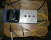
I built a resistance soldering device out of scrap parts.

It works 100 % , but I would like to vary the secondary voltage.

What should I use ?

I have tried a lighting dimmer switch , and that does not work.

Any suggestions ?

My transformer is 120 volt primary and 16 volt secondary.
 
maybe if you posted some pictures and a schematic someone might be able to help you.
 
maybe if you posted some pictures and a schematic someone might be able to help you.


I would have to draw it out , but for now I will just describe it.

Line - 120 volt in ... through a line switch, an indicating light and a 15 amp fuse.

The secondary leads have each an alligator clip.

One clip is clamped on to the metal that has to be soldered , the other clamp holds a carbon rod.

Get the picture?

I just hold the carbon rod to the other part to be soldered , and the area between gets hot immediately.

I just apply the solder, then break the contact from the carbon rod.

Like I said, it works great.

But I would like to have more control.

Eventually I will use a foot switch.
 
hi,
One option to control the transformer secondary voltage of the transformer, would be to use a Variac transformer to drive the 120V primary.
E
 
Your carbon rod has an intrinsic resistance. For decreased output voltage, use a longer carbon rod ... more resistance ... less current. Also, a smaller diameter carbon rod might give you less output voltage.

For more output voltage, you will probably have to arrange for a second transformer, with secondary windings, in series, with your original secondary. Transformers have a maximum volt-amp specification, which limits the power that each will tolerate.
You can set up a serial, additive, secondary, output by measuring the voltage across the two open leads. That is, the two interior leads will constitute the serial connection node. If you don't get 32 output volts, then reverse one of the secondary winding polarities. ... Not too complicated.
 
A key missing fact is how much power is this thing drawing. Or if you don´t know, then how big is the center part of the core in the transformer.
 
If you want to control the secondary directly, you are talking about some pretty high current, and it is AC, so things like mosfets will present a problem.

Another approach, which I used for my resistance welder, is to use a timer for the primary. I used a 555-based one-shot timer. I could vary the timing as needed. The one-shot controlled a solid state AC relay. The relay was a Continental S505-OSJ410-000 and was scavenged from a refrigeration unit. The Crouzet equivalent is 84134000. The relay is zero crossing.

John


Thanks to all you guys.

I found a variable resistor in my parts bin.

I tried it on the primary, yep it works !

You were the inspiration !

:happy:
 
That must be one heck of a resistor!
 
Hi,

I would not mind seeing some pics of the complete setup, the resistor, and even a joint before and after soldering, especially 'after'. I dont like resistance soldering but if i see a nice joint i might be convinced otherwise.

It is possible to use a lamp dimmer on the primary, but you also should have a nice resistance load too like a 100 watt light bulb. So you'd be controlling the transformer but also the light bulb in parallel with the secondary. I think that would work too. But if your resistor works and you are satisfied with the results, that's fine too.
 
The issue with ordinary lamp dimmers is that they often do not trigger the internal scr uniformly, so upper and lower waveforms are not equal, effectively placing dc across the transformer overheating the latter.
On this device however your probably only applying juice for a second or 2, so if you wired it up so that the transformer only gets powered while soldering it'll probably do ok unless your doing long manufacturing runs.
 
I think we need a lot more information on the device Al Manzoli built. When you mention a second or two of heating , that may be way too long or too short, depending on the device that was built. On the device I built with the NE555 circuit described above, thin-gauge steel got quite hot within 170 mS (i.e., about 10 cycles of 60 Hz current). My welder/heater was made from a microwave oven transformer with a few turns of heavy gauge welding cable as the secondary.

John
 
P9270005.JPG
I think we need a lot more information on the device Al Manzoli built. When you mention a second or two of heating , that may be way too long or too short, depending on the device that was built. On the device I built with the NE555 circuit described above, thin-gauge steel got quite hot within 170 mS (i.e., about 10 cycles of 60 Hz current). My welder/heater was made from a microwave oven transformer with a few turns of heavy gauge welding cable as the secondary.

John

I may have jumped the gun on the success of my variable resistance.

B T W , I wrote variable resistor, but I meant variable resistance.

It is an Ohmite Rheostat ... 588-RKS-1K RKS1KO.

On further experiments , I realized it is not giving me the control that I would like.

The other part of the problem may be the carbon rod that I am using.

It is the core from a zinc carbon D Cell battery.

I will try all your suggestions , but first I will try to get a carbon arc rod from a welder friend.

Here is a pic of my device.... Sorry if it is not too clear !
 

Attachments

  • P9270005.JPG
    P9270005.JPG
    4.1 MB · Views: 239
  • P9270005.JPG
    P9270005.JPG
    4.1 MB · Views: 218
Hi,

I would not mind seeing some pics of the complete setup, the resistor, and even a joint before and after soldering, especially 'after'. I dont like resistance soldering but if i see a nice joint i might be convinced otherwise.

It is possible to use a lamp dimmer on the primary, but you also should have a nice resistance load too like a 100 watt light bulb. So you'd be controlling the transformer but also the light bulb in parallel with the secondary. I think that would work too. But if your resistor works and you are satisfied with the results, that's fine too.


When you say , a 100 watt light bulb in parallel with the secondary , that sounds like it should work .

The light bulb just acts as a resistance , therefore it does not matter that the light bulb is a 120 volt bulb .

Am I correct in assuming this?

If this works , what would happen if I put a dimmer switch in series with the light bulb ?

Will this give me a little more control of the heat ?

th_Smiley-Question.jpg

I realize these all sound like dumb questions , but Ohms law says it should work !
 
That looks prensentable.

Industrial spot welders use a 'timer' to control the weld heat, simpler ones just count the number of half cycles fed to the load, that might be a good way to look into, it doesnt create any problems with switching harmonics and the like.
 
Status
Not open for further replies.

Latest threads

Back
Top