Continue to Site

Welcome to our site!

Electro Tech is an online community (with over 170,000 members) who enjoy talking about and building electronic circuits, projects and gadgets. To participate you need to register. Registration is free. Click here to register now.

  • Welcome to our site! Electro Tech is an online community (with over 170,000 members) who enjoy talking about and building electronic circuits, projects and gadgets. To participate you need to register. Registration is free. Click here to register now.

Resetting DS3231 RTC

Status
Not open for further replies.

jpanhalt

Well-Known Member
Most Helpful Member
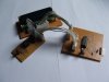
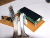
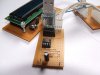
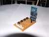
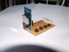
After many delays, I finally put some constructive time into my 16F1829 I2C interface with an imported DS3231 RTC module. Long story, short, using a scope on SCL and SDA really helped.

Initial program had a couple of short cuts that didn't work like I hoped (based on MCC's ap notes) they would. The RTC was either in an unknown state or quickly became that way. It would not release the SDA line, so there was a constant error. Unplugged the RTC, and the program seemed to simulate fine, but I could not get the RTC as slave to release the SDA line. (I know what its datasheet says to do.) Removed it, rubbed the pins, let it rest awhile, and low and behold, it reset to a known state. When it was plugged into the test board, SDA was high. The rest of the trip was downhill.
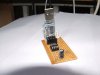
Here's a snapshot:
upload_2016-2-9_10-52-35.png

Seconds are on top and minutes below. Soothing to watch the seconds tick away and watch them on the scope simultaneously.

Question: The DS3231 datasheet says simply to keep pulsing the SCL line until it releases the SDA line and lets it float high. Is there a way to do that using the MSSP module? That is, can you just start the clock alone without regard to the SDA status?

Regards, John

EDIT: Forgot to mention language is MPASM
 
Last edited:
Maybe the absence of replies is evidence of absence within the MSSP module. On to Plan B. This bit-banged ISR gives the right pulse train on simulation. Only problem is, I haven't been able to duplicate the condition in which the slave (DS3231) held SDA low again. So, I can't test it for real. Anyway, here's the ISR that should unlock it, if and when that ever happens:
Code:
;*******************************************************************************
;                        INTERRUPT SERVCE ROUTINE
;*******************************************************************************
     ORG       0x0004
     movlb     0              ;                                                 |B0
     bsf       LedBCL         ;                                                 |B0
     DelayCy   (60*msecs)
     movlb     4              ;                                                 |B4
     bcf       SSP1CON1,SSPEN ;disable serial port and allow I/O on pins        |B4
     movlb     1              ;                                                 |B1
     movlw     b'00010000'    ;SCL is bit<6>, make output                       |B1                   
     movwf     TRISB          ;avoid R-M-W on TRIS                              |B1
     movlb     0              ;                                                 |B0
     bcf       PIR2,BCL1IF    ;clear bus collision flag                         |B0
;set up TMR2 to repetitively pulse SCL until SDA goes high
     bsf       T2CON,TMR2ON   ;turn TMR2 on                                     |B0
     bsf       PORTB,SCL      ;                                                 |B0
Pulse
     bcf       PIR1,TMR2IF    ;
     btfss     PIR1,TMR2IF    ;PR2 set to 10 cycles in Start                    |B0
     bra       $-1            ;                                                 |B0
     movlw     b'01000000'    ;                                                 |B0
     xorwf     PORTB,f        ;                                                 |B0
     btfss     PORTB,SDA      ;                                                 |B0
     bra       Pulse          ;                                                 |B0                 
     reset                    ;need clarify effect of reset on stack            |B0

;     retfie
The pulse frequency is about 91 kHz with the MCU @ 8 mHz, which should be close enough.
John
Edit:Changed clrf SSP1BUF to movf SSP1BUF,w to clear BF flag. Early morning oversight.
Edit2: BF is cleared on all resets, so that line was deleted too.
 
Last edited:
Just to keep things updated, I've EVENTUALLY started playing with one of my RTC's (after the first delivery of them got 'pulverised' on the way from China - even the batteries were damaged and bent).

I've just put it on a board with four push-button switches, so it plugs in as part of my usual tutorial boards.

The software I'm using is written in XC8, and I found it on the net, for an 18F4520 - and I simply changed the code for my new PIC of choice the 16F1827, and changed the LCD pinouts to match my tutorial boards, and used the hardware I2C MSSP interface of the PIC.

It all went quite nicely, and it's sat running a nice clock at the moment :D
 
Hi Nigel,

Glad the second shipment arrived safely. I have been busy learning some interfaces and have now put everything onto one board. The open socket on the lower left is for a WWVB (USA) receiver. My program to capture the "zero" second transition is working -- just TMR0 counting transitions. And my sync (I2C) with the RTC is also working. My project now is to integrate them into a 16F1829 so I can see in ms how much drift the RTC has per day. Spring is seemingly early here, so that will afford me the opportunity easily to see what effect ambient temperatures have on that drift.

Just FYI, here's my board:
upload_2016-2-22_16-47-25.png


Upper left is ICSP, lower right are some switches for "doing things," upper right is the RTC. The three LED's help me troubleshoot programs, since MPLAB doesn't simulate some functions, such as capture on all chips. Top center is the power plug. When programming, I use the USB 5V source. On my bench, I use a couple of LiFe batteries in series with a little regulator and an MCC charger.

John
 
The PIC costs about the same as a machined-pin socket for it. ;)

It is my first time with a solderable breadboard. The SparkFun version ($4.95) looks nice and has plated through holes -- some versions from other vendors don't. The only thing I don't like is that the power rail holes do not line up with the 5-hole signal traces. That completely disrupts my sense of symmetry and accounts for all of the dog legs. Actually, working on a solderable board was not that bad. I switched to 24 AWG Kynar ( wire wrap) wire from 22 gauge. That gauge was easy to work with, and the Knyar was more stable to soldering heat than PVC insulation. The picture I posted already had one rip-up and re-routing to get my switches in different pins.

As for confidence, the only element of the program I didn't have working on the 16F1829 was reading the WWVB receiver, which was working on a 12F1840. Moving that over to the 16F1829 was just a matter of changing from CCP1 to CCP3 and setting the ports right. The 16F1829 gives me enough pins so I can run TMR1 off a 32 kHz watch crystal and then up the MCU to 8 MHz from its current 2 MHz. So, I figured it wasn't that big a risk considering.

In the interim since our last conversation, I have bought a really cheap ($5) and a more expensive ($20, Target) LaCrosse Tech. WWVB clock. The latter is the biggest wall clock I could find at a low price. I hope it has a better antenna than the little receiver I had. At least the big wall clock gets signal and synchronizes during the day. I am waiting for my cheapie before I open the wall clock.

Best regards, John
 
Hi,

Just wondered if anyone was using this type of ds3231 module and if its equally little battery (instead of the usual cr/lr 2032 ) is a type that can be readily found in the uk ?

000262.jpg

ps - has anyone else found problems logging on or uploading jpegs when using firefox v44? - works ok with chrome ..
 
I am using a very cheap DS3231 module off ebay. The only reason I used an expensive socket for it is that I want to compare three modules ($1.50 each including shipping) for drift.
My general plan is to program each module to give a 1 second tick and compare that tick to WWVB's one-second tick.

I use Chrome, so cannot comment on Firefox.

John
 
Hi Again,

If you do not mind the interuption, a couple of points would like to mention.

Despite looking around the web at various well known sites, there still seems to be a great deal of variation regarding the RTC modules pullup resistor values for the I2C lines.
Most DS1307/3231 seem to come with 4k3 or 4k7 resistors fitted , though some suggest 10k is the minimum Philips recommend for the bus.
Equally you see suggestions for as low as 1k8.
It becomes even more confusing when, as I have just done, you use 2 devices on the I2C bus, eg a Ds3221 and a LCD to IIC serial module.
Have been testing them together and they do seem to work ok, but the paralled pullups mean its effectively 2k3.

While begin a Pic Assembly old timer like you and NG I am doing the above with the Arduino and thier IC2 library seems to have a shortcoming which this site offers code to overcome the problem.
Though its in C++, think the problem may be experienced with your assembly routine ? though the solution method should be easy enough to convert to assembly if needed.
https://www.forward.com.au/pfod/ArduinoProgramming/I2C_ClearBus/index.html
 
Despite looking around the web at various well known sites, there still seems to be a great deal of variation regarding the RTC modules pullup resistor values for the I2C lines.

It really doesn't matter at all - particularly as PIC's have ports with high current drive source and sink capabilities.

Obviously the entire idea of I2C was for TV's, with chips connected to a common bus with a single pair of resistors near the CPU - and in this use you could get quite long PCB traces on the I2C rails, hence the need for lower value resistors to rapidly charge the resulting capacitance.

'Generally' 4.7K seems to the most common value these days - but in my tutorials I used 18K, which I happened to have to hand, and work perfectly fine.
 
I am using 4K7 pull-up resistors:
upload_2016-2-27_7-6-9.png


The color is not great, and I can never tell brown from violet without a DMM or very good light anyway. I went with 4K7 based on some comments on the Microchip forums. Even lower values are recommended for 400 k baud or Hz(?) I2C. I am just using 100 k. Most everything is working with either a WWVB emulator or real signal, but I have to get up earlier than usual (2 AM EST, USA) to get a good real signal. I tend to start my days early and end early, rather than the other way around.

Right now, I am concentrating on getting a better antenna. Mike (K8LH) gave some good links. I am leaning toward a shielded loop or open loop design.

One question: Almost every source I check uses an inverted WWVB signal. Of course, changing from reading a non-inverted to inverted signal was easy in the PIC, but is there a reason for the apparent preference for the inverted signal?

John
 
One question: Almost every source I check uses an inverted WWVB signal. Of course, changing from reading a non-inverted to inverted signal was easy in the PIC, but is there a reason for the apparent preference for the inverted signal?

Is it a standard RS232 type signal?, in which case it is inverted as the level converters invert the signal as well as converting it from 0-5V to +12/-12V.
 
The signal levels depend on the power supply and chip. The standalone receiver I have is 5V for high. The one I salvaged from a clock is will work down to about 1.5V, but I believe it is intended to work from a single photocell of about 3V.

There are 6 frames per minute; each is 10 seconds. Each bit is 1 second (i.e., 10-bits per frame/byte) Only the first frame has a start bit. Each frame has a stop bit. Most of the coding is BCD. Although superficially, one might think it is 9+1, in reality, there is an ignored bit in each frame, so it all fits into an 8-bit register. I would not call it typical RS232.

The really exact time that WWVB "guarantees" is the high-to-low transition for the start bit (stop bit ends high). That is 00.n? seconds. Here is a pdf link with a more complete description. The transmission protocol is on page 17/68 of the pdf.

https://tf.nist.gov/general/pdf/2422.pdf

John
 
OK, I promised pictures, so here's some of the tutorial boards I've recently constructed - the EEPROM_USB one just this morning in fact.

So there's a new LCD board, which connects to PortA (usually) of the tutorial boards. An EEPROM board with a TTL/USB serial converter on it - for obvious data logging purposes. And finally, an RTC board with four buttons on it as well.

The main board I'm using is a 16F1827 board (my new PIC of choice), and I'm using XC8 for the software.
 

Attachments

  • Complete.JPG
    Complete.JPG
    1 MB · Views: 296
  • EEPROM_USB1.JPG
    EEPROM_USB1.JPG
    967.8 KB · Views: 306
  • EEPROM_Display1.JPG
    EEPROM_Display1.JPG
    1,007.1 KB · Views: 297
  • EEPROM_Display2.JPG
    EEPROM_Display2.JPG
    1,000.9 KB · Views: 318
  • RTC1.JPG
    RTC1.JPG
    969.7 KB · Views: 291
  • RTC2.JPG
    RTC2.JPG
    971.9 KB · Views: 308
The main board I'm using is a 16F1827 board (my new PIC of choice), and I'm using XC8 for the software.
I wonder if that's a good choice, Nigel? It seems Microchip isn't doing much with the 18-pin devices. All of the new and exciting 1500, 1600, 1700, and 18000 series devices are coming in 8, 14, 20, 28, and 40 pin packages. Also worth mentioning, the 8, 14, and 20-pin devices share a somewhat common I/O pin organization (see below).

Oh, BTW, your tutorial boards look very nice...

Proto Front (cropped).png Proto Read (cropped).png
 
Last edited:
I wonder if that's a good choice, Nigel? It seems Microchip isn't doing much with the 18-pin devices.

It's a natural progression from the 16C84, 16F628, and now the 16F1827(1847), and of course it's pin compatible.

For my tutorials it makes little difference, as all 14 bit PIC's are VERY similar - even the enhanced ones I use now are upwards compatible from the older ones.

All of the new and exciting 1500, 1600, 1700, and 18000 series devices are coming in 8, 14, 20, 28, and 40 pin packages. Also worth mentioning, the 8, 14, and 20-pin devices share a somewhat common I/O pin organization (see below).

Bit weird pin numbering?, only one full port out of the three.

I 'think' they do a 20 pin version of the 1827, but it's got no more I/O than the 18.

Oh, BTW, your tutorial boards look very nice...

View attachment 97825 View attachment 97826

That's very nice, although I was a bit shocked to see the bottom - as I presumed it was a silk-screened PCB from the top picture :D
 
Status
Not open for further replies.

New Articles From Microcontroller Tips

Back
Top