sazerac99us
New Member
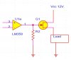
I know this is pretty basic stuff, but i want to do it right...this circuit, uses the output of an LM358 op amp to drive a BC548 transistor, which either drives a small load, or a relay, for a bigger load.
My questions is this. The load I want to drive is in the range of 1 amp DC, and I'd rather drive it with a transistor than a relay. The problem, is that I dont think the out put of the LM358 is enough to drive a big enough NPN (with their much lower gain) to handle 1 amp hard enough to saturate it. Is it bad practice to drive a pair of the smaller VC548s, and use them in parrallel to handle larger amounts of current?
Any ideas or circuit diagrams will be greatly appreciated.