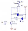
See the attached schematic for current circuit. The IN is +5v coming from computer and when present the relay is engergized. There are 8 of these which control a bi-color 7 segment LED display. The display has 2 common anodes, one for green and other for red and 7 cathodes. Seven of the cathode relays are used to switch on the display's segments by going to ground. The 8th relay is wired by N.C. leg to green anode and N.O. leg to red anode. The supply to common leg of anode relay is currently +5v but can be 5-12v.
I want to replace the mechanical relays with a solid state solution since I think it is overkill to control 5v circuit with relays. So I would like to replace with a SS device that would cause the LED cathodes to go to ground. I'm not planning to use any of the components in the current circuit but build everything new. Also the anode circuit needs needs to be a double throw type to control green and red colors. If I could control the segments by switching voltage like the relay coils are done now, I could just use the same circuit and substitute a SS device for the relay I think, but I need the inverse, ie, go to ground switching.
I want to replace the mechanical relays with a solid state solution since I think it is overkill to control 5v circuit with relays. So I would like to replace with a SS device that would cause the LED cathodes to go to ground. I'm not planning to use any of the components in the current circuit but build everything new. Also the anode circuit needs needs to be a double throw type to control green and red colors. If I could control the segments by switching voltage like the relay coils are done now, I could just use the same circuit and substitute a SS device for the relay I think, but I need the inverse, ie, go to ground switching.
Attachments
Last edited:
")