Continue to Site

Welcome to our site!

Electro Tech is an online community (with over 170,000 members) who enjoy talking about and building electronic circuits, projects and gadgets. To participate you need to register. Registration is free. Click here to register now.

  • Welcome to our site! Electro Tech is an online community (with over 170,000 members) who enjoy talking about and building electronic circuits, projects and gadgets. To participate you need to register. Registration is free. Click here to register now.

Relay issue - Driving signal input with 5V+ digital wire

Status
Not open for further replies.

bhollehday

New Member
I bought this relay from amazon:

https://www.amazon.com/gp/product/B00LW15D1M/ref=ppx_yo_dt_b_asin_title_o04_s00?ie=UTF8&psc=1

Im trying to drive it with Adafruits lase breakbeam sensors:

https://www.adafruit.com/product/2167


Which shows a 5V+ for the signal wire

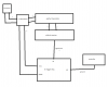
I hook it up to the relay with the jumper on HI, and the light turns on but relay doesn't click. I turn the jumper to low and it clicks, but dosen't turn off when beam is broken. I measure the voltage on the signal wire and it measures 5V+ unbroken, and I get open circuit small mA reading.

I have a 10K ohm resistor between power and signal as specified by the datasheet for the sensors.

The relay works with a ground as a signal on jumper low setting, but I feel like its not reading the drop in voltage when jumper is on high setting.

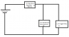
The relay is wired to 24V and the sensors are regulated with a 5V ps. Can someone help?


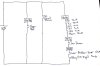
Ultimately I need to use the relay to drive a ground as a input signal to a controller that only reads a ground. I want to use the relay to read the positive digital signal, and output a ground to the controller.
 
unfortunately your link shows 12V coil relays.
 
It means the relay in your link is designed for a +12V input to trigger (or at least to power the +12V relay itself), according to the text....
They do make +5V trigger relays, but that is not one of them.
 
the sensors do not provide enough current to drive the relay. you need to use a transistor to drive the relay coil. you need the relay power to be 12vV dc, and the relay coil acts as the collector (for a bipolar transistor) or drain (for a MOSFET) load. the sensor would be connected to the base or gate of the driver transistor. an example of a relay driver transistor is this:
relay-driver.png

the control signal can be a 5V logic level, or the output of the sensor.
 
Ok new problem. I have the adafruit break beam sensors and they are working using a 5V trigger relay, but they are a little too sensitive. I need to drive
the sensors with 3.3v instead of 5v. I tried this relay module:

https://www.amazon.com/gp/product/B0798CZDR9/ref=ppx_yo_dt_b_asin_title_o05_s00?ie=UTF8&psc=1

But it dosent seem to work. It triggers when I drive it to a 5V source, so I guess my thinking it will work with a 3V trigger source was wrong...

When I remove the 10K ohm resistor between the signal wire and the power wire of the sensors, the signal wire reads 6V and almost 0 when beam is broken.

I'm getting further lost in the wrong direction, could anyone tell me what i'm doing wrong (or what i'm doing right!) or recommend something?
 
What is supplying the VCC for the input on that board? It should be 3V (3.3V?) with at least 150mA current capacity. That relay draws between 120mA to 150mA, depending on sensitivity, at 3V. That is, you have to supply a separate source of 3V for that relay, then just trigger it with your micro/detector via the "IN" line between 0 to 3V trigger You cannot power it with any micro pin directly, as most I/O ports are limited to 20 or 25mA
Putting 5V on that VCC may overheat the relay, and burn it out eventually..

Also the Amazon listing states:
"When the jumper cap connected, the relay working power supply will also as the signal power supply, when not connected, the relay and signal power supply is isolated. "
Keep that in mind....


Im supplying from a step down regulator for 3.3V with an 800mAh current limit. Why do you have to supply a separate source? What are you referring to as a micro pin? Are the I/O ports and micro pins your referring to from a logic based controller? My controller can do sinking up to 50mA. So being I have to use two seperate power sources, one for the sensors and one for the relay, I should remove the caps on the relay, correct?
 
Im supplying from a step down regulator for 3.3V with an 800mAh current limit. Why do you have to supply a separate source? What are you referring to as a micro pin? Are the I/O ports and micro pins your referring to from a logic based controller? My controller can do sinking up to 50mA. So being I have to use two seperate power sources, one for the sensors and one for the relay, I should remove the caps on the relay, correct?

Post an EXACT circuit of what you're doing, vague descriptions are useless, we've no idea what you might be doing.
 
What is the 5V source? Can it supply the 800mA that the 3.3V converter needs (technically). Of course if all the loads are a lot less than 800mA, and the 5V supply can sothen no issues. Just want to verify the 5V supply has the current capacity...
Also, make sure the adafruit receiver ground is connected the the relay module ground.
 
I have a couple of questions for clarity on this sensor:

https://www.adafruit.com/product/2167
  • Emitter Current Draw: 10mA @ 3.3V, 20mA @ 5V
  • Output Current Capability of receiver: 100mA sink
What does 100mA sink mean exactly? I interpret that as the signal wire of the receiver can drive 100mA? But my understanding is that sink means ground. And the datasheet of the sensor shows 5V+ for the signal wire.

here is a better interpretation of what my circuit looks like also...

I bought these from amazon hoping I can take any signal these sensors put out, and convert it to a logic signal...

https://www.amazon.com/gp/product/B07F7W91LC/ref=ppx_yo_dt_b_asin_title_o00_s00?ie=UTF8&psc=1
 

Attachments

  • IMG_3592.JPG
    IMG_3592.JPG
    151 KB · Views: 97
100mA sink means it can conduct (sink) up to 100mA of current to "ground" when in low state. That is, when active, its signal line drops to low, and sinks current form whatever it is interfaced to. It does not mean it can source any current. If the device sinking the 100mA is an open collector type of device, it will not source any current at all. The "high" state is held high by the device you are interfacing to (the relay board)
Your relay interface "in" pin is normally high, and you "sink" the line low to trigger the relay....
 
Last edited:
Status
Not open for further replies.

Latest threads

New Articles From Microcontroller Tips

Back
Top