ThomsCircuit
Well-Known Member
Part# NA12W-K
Datasheet= Taydel Electronics
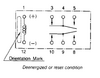
Why does this have a polarity? I like it because its small and this version is a SPDT. I use it to trigger a larger relay coil and illuminate an LED as shown in this schematic.
Im concerned because the datasheet has no mention of it.
Datasheet= Taydel Electronics
Why does this have a polarity? I like it because its small and this version is a SPDT. I use it to trigger a larger relay coil and illuminate an LED as shown in this schematic.
Im concerned because the datasheet has no mention of it.
")
