Continue to Site

Welcome to our site!

Electro Tech is an online community (with over 170,000 members) who enjoy talking about and building electronic circuits, projects and gadgets. To participate you need to register. Registration is free. Click here to register now.

  • Welcome to our site! Electro Tech is an online community (with over 170,000 members) who enjoy talking about and building electronic circuits, projects and gadgets. To participate you need to register. Registration is free. Click here to register now.

Relay circuit with battery backup

Status
Not open for further replies.

ibwev

Member
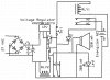
I am trying to assemble a circuit using 12 volt Energizer A23 batteries as a backup. If switch 2 is opened, I would like the alarm and light to activate even if there is a loss in power.

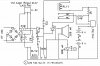
1) Is the attached circuit functional?

2) The capacitor raises the voltage to the voltage regulator near the max for the voltage regulator.
a) Is the capacitor necessary for the circuit? If it is, would a smaller capacitor be sufficient?
b) Is the voltage regulator adequate for the circuit?https://www.fairchildsemi.com/ds/KA/KA278R05C.pdf
 

Attachments

  • Schematic2.jpg
    Schematic2.jpg
    110.6 KB · Views: 187
Right now it looks like R2 is picked with power on so the buzzer would sound. You can move the buzzer and LED to the N/C.
The A23 battery is way to small to drive 600ma. It's voltage would drop to almost nothing with that load.
You will need a series resistor to limit the current for the LED unless it has one built in.
You could probably use a LM317HV for the regulator.
 
The energizer A23 battery is tiny and its very low power is used occasionally as a remote car door opener.

Its datasheet shows that it can supply 0.6mA for 55 hours at which time its 12V drops to 6V.
It might supply 10mA for 30 hours.
It might not be able to supply 25mA or more.

You need nine AA alkaline cells in series for battery backup that will last for 4 hours..
 
Right now it looks like R2 is picked with power on so the buzzer would sound. You can move the buzzer and LED to the N/C.
Thanks. Changed in attached schematic

You will need a series resistor to limit the current for the LED unless it has one built in.
The LED I am using has built in resistors.

You could probably use a LM317HV for the regulator.
I tried to follow the formula on page 7 of the LM317HV datasheet. Are the 240 Ω and 2K Ω resistors correct to produce 11.9 volts? 1.25(1+(2000/240))+0.0001(2000)

You need nine AA alkaline cells in series for battery backup that will last for 4 hours..
Would 2- 9 volt batteries in series along with the LM317HV voltage regulator adequately power the alarm and light. According to Wikipedia, the zinc-carbon 9 volt battery contains about 400 mAh.
 

Attachments

  • Schematic3.jpg
    Schematic3.jpg
    126.5 KB · Views: 170
Nobody uses antique carbon-zinc 9V batteries today but very cheap Chinese toys come with leaking carbon-zinc batteries.
A normal 9V battery today is alkaline and it is rated at 625mAh when its load is 25mA. Then its voltage has dropped to only 4.8V.

You copied the schematic for an expensive LM117HV that can use a 240 ohm resistor. The cheaper LM317HV needs a 120 ohm resistor when its load current is less than 5mA to prevent its output voltage from rising. The datasheet explains it.

Two 9V alkaline batteries in series will produce 18V when new but their voltage slowly drops when they are used. You can use an ordinary LM317 instead of the high voltage (HV) version. The two batteries might power the 600mA circuit for a few minutes. If the circuit is not used then the continuous idle current of the LM317 will kill the batteries in about 63 hours (less than 3 days).
 
You copied the schematic for an expensive LM117HV that can use a 240 ohm resistor. The cheaper LM317HV needs a 120 ohm resistor when its load current is less than 5mA to prevent its output voltage from rising. The datasheet explains it..
Thank you for the help with the circuit. Please help me understand where this is explained in the datasheet https://www.ti.com/lit/ds/symlink/lm117hv.pdf . The closest schematic I have seen for using the LM317HV as a 12 volt regulator is figure 37 for a 12 volt battery charger. If my math is correct, figure 37 would produce 13.9 volts [ 1.25(1+(2400/240))+.00005(2400)]. Should I follow figure 37 or the schematic on page 7 with a LM317HV instead of the LM117HV using 120 Ω for R1 and 1000 Ω for R2 to yield 11.7 volts?
 
Correct me if I am wrong, but, the way I read the DS for these for the minimum load is that the VREF is 1.25V, for the 317 it states 3.5mA to 12mA, so I usually assume 10mA as an average figure, if it is the 117, it states 3.5mA to 7mA, I usually assume 5mA as an average figure, using OHMS law, 317 should be 120R and the 117 should be 240R to maintain minimum load.
 
For a 12V regulator why are you using the more expensive High Voltage version (LM317HV) instead of a cheaper ordinary LM317?

The datasheet for the LM317 says that its minimum load current is 10mA so the voltage-setting resistor is 1.25V/10mA= 125 ohms so a 120 ohm resistor should be used. The datasheet explains, "If there is insufficient load (current) on the output, the output (voltage) will rise. You do not want the output voltage of a voltage regulator to rise so you need to load it enough.

For the LM117 the minimum load current is 5mA so the voltage-setting resistor can be 1.25V/5mA= 250 ohms so a 240 ohm resistor can be used.
 
For a 12V regulator why are you using the more expensive High Voltage version (LM317HV) instead of a cheaper ordinary LM317?
Thank for the help and explanation. I am using the high voltage version of the LM317 because it was suggested to me by another member; however, after looking at the specs of the LM317, it appears the input voltage can be as high as 40 volts and my supply should be less than 35 volts past the capacitor so the cheaper LM317 should work. I really appreciate all the help you have provided.
 
Status
Not open for further replies.

Latest threads

New Articles From Microcontroller Tips

Back
Top