Continue to Site

Welcome to our site!

Electro Tech is an online community (with over 170,000 members) who enjoy talking about and building electronic circuits, projects and gadgets. To participate you need to register. Registration is free. Click here to register now.

  • Welcome to our site! Electro Tech is an online community (with over 170,000 members) who enjoy talking about and building electronic circuits, projects and gadgets. To participate you need to register. Registration is free. Click here to register now.

Regulators failing

Status
Not open for further replies.

Diver300

Well-Known Member
Most Helpful Member
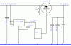
I have an LM25576 regulating approximately 12 V down to 4 V. The LM26676 is a buck switching regulator and in my power supply it is rated to 2A. It has a soft start capacitor so that the output voltage comes up fairly slowly.

From that I am feeding a ZXCL300 to give me 3 V at a few mA.

The problem is that as I turn on the 12 V, the ZXCL300 sometimes goes up in smoke.

I've looked at the 4 V line with a scope and there don't seem to be any spikes, but I am not entirely sure. When I switch on the 12 V with a transistor there isn't a spike and I can just see the ramp controlled by the LM25576. There is a 100 uF capacitor on the output of the buck regulator, and a couple of ceramics as well.

Any ideas?
 
We can't help you with anything unless you post the entire schematic of your circuit.
 
Why don't you put a couple of diodes to drop the voltage. The chip you are using is obviously a very delicate device.
 
What is being powered off of the ZXL part? Maybe something is latching up.
 
Or the SMPS isn't set up correctly and it's getting straight 12 volts for some fraction of a cycle. There's any number of a hundred things that could be going wrong and we could guess until the cows came home but we can't offer any advice without a schematic. There should be a lock on all threads like this without schematics because they drag on for 3-5 pages and usually then the poster comes out with some random bit of information that if inclded in the original post would have led to an immediate answer. But they get bogged down in what ifs and people aruging about symantics from a circuit that isn't even fully defined.
 
See. The what ifs are already starting =)
 
You mean like, What if something, something, something, something, 555 timer IC, something, something, something, something, Microcontroller, something, something, something, something, SMPS, something, something, something, something, super ultra multistage battery charger,something, something, something, something, line harmoncs.

Is that what you are saying? :D
 
Here is the schematic. I should have posted it when I started the thread.

I am running a PIC from the 3V line, and using the 3V as the ADC source, so I want a well-regulated voltage.

I don't think that the PIC is taking excessive current. I've never blown one of them. The ZXCL300 should have thermal shutdown to protect it against too much current.
 

Attachments

  • regulator1.gif
    regulator1.gif
    21.1 KB · Views: 302
Why such a complex buck psu when you could just use an 7805 for 5v rail, and an LM317LZ for the other 4V and 3V rails. Assuming the current draw is less than 100mA per reg.

sPuDd..
 
These devices get damaged much faster with excess voltage, rather than excess current. Try putting a large inductor on the input line to the regulator and put an electro both ends of the inductor.
 
Why such a complex buck psu when you could just use an 7805 for 5v rail, and an LM317LZ for the other 4V and 3V rails. Assuming the current draw is less than 100mA per reg.

sPuDd..

2 Amp peaks on the 4 V rails.

1/2 amp continuous on the 5 V rail.

It can run from 24 V. With a linear regulator I would dissipate 10 W continuous. At the moment, I don't have a heat sink.

I like Colin55's idea of an inductor, even if I never find the real cause.
 
The first thing I'd try is using a 100n capacitor at the ZXCL300 input and output pins.

If it oscillates at a very high frequency, which you haven't checked yet it fries to death.

Boncuk
 
Here is the schematic. I should have posted it when I started the thread.

I am running a PIC from the 3V line, and using the 3V as the ADC source, so I want a well-regulated voltage.

I don't think that the PIC is taking excessive current. I've never blown one of them. The ZXCL300 should have thermal shutdown to protect it against too much current.

Put one 0,1uF cap across input and Gnd of the ZXCL300. Instead, you may also use a conventional TL431 and few components around to get 3.3V or even 3.0V
 
Looking at the Zetex data sheet and the current boost circuit with the ZXCL300 I see a 1µF capacitor each at the input and output pins.

(I guess they're not there for fun. Zetex obviously knows about the oscillation tendency of that chip.)

Using two additional 100nF capacitors won't hurt or be astronomically expensive but keep the regulator alife.

Boncuk
 
Looking at the Zetex data sheet and the current boost circuit with the ZXCL300 I see a 1µF capacitor each at the input and output pins.

(I guess they're not there for fun. Zetex obviously knows about the oscillation tendency of that chip.)

Using two additional 100nF capacitors won't hurt or be astronomically expensive but keep the regulator a life. Boncuk

You are right Boncuk. the schematic already has one electrolytic . i have now added another disc cap on the output also. this is how it looks now.
 

Attachments

  • POWER CCT modded.PNG
    POWER CCT modded.PNG
    48.1 KB · Views: 275
Last edited:
Please post if it turns out to function properly.

Thanks

Boncuk
 
Well it turns out that I hadn't told you the whole story, because I had been making assumptions about the source of the problem.

I had been looking for voltage spikes, as I had assumed, as colin55 said, that voltage is what usually kills these things.

In this case it was current.

Flowing backwards through the regulator.

After many tests I found that additional capacitors made no difference, but I noticed that the regulator would not fail unless the PIC was programmed.

Following that up, I found that it was the action of turning on the mosfet that killed the regulator. If I left it turned off, or linked it out, the regulator was fine.

What was happening was that the 4V line would rise from zero to about 3V. That is controlled by a ramp capacitor and is quite slow. If at the point, the 12 V input was disconnected, due to switch bounce, the 4 V supply stayed at 3 V and only decayed slowly. When the PIC turned the mosfet on, the two additional 100 µF capacitors pulled the 4 V line down.

The body diode within the ZXCL300 turned on, and pulled down the voltage on the 10 µF capacitor. That exceeded the 30 mA reverse that the diode is rated at. I think that caused the ZXCL300 to latch up and effectively short out the 4 V supply.

If that was the moment that switch bounce caused the 12 V to be applied, the full short-circuit current from the 4 V, 2 A supply was conducted to ground through the ZXCL300, causing the smoke.

The software fix is to delay turning on the mosfet for several seconds, to make it far less likely that the 12 V is off and will turn on a few ms after the mosfet. If the 4 V supply is at 4 V and running when the mosfet turns on, the voltage dips much less, and there isn't much, if any, reverse current in the ZXCL300.

The hardware fix is a schottky diode across the ZXCL300 so that the 10 µF capacitor can be discharged back to the 4 V line without causing latch-up in the ZXCL300.

I am guessing about the latch-up. The ZXCL300 data sheet says that 5 mA continuous and 30 mA peak is what is allowed backwards through the regulator. I am exceeding that, but I had thought that the energy stored in a 10 µF capacitor at 3 V wouldn't do any damage. However, I hadn't considered latch-up. The data sheet for a competitor's product, the **broken link removed** doesn't allow any reverse current and mentions latch-up, so I think that is what is happening.
 

Attachments

  • regulator2.gif
    regulator2.gif
    9.8 KB · Views: 271
What is being powered off of the ZXL part? Maybe something is latching up.

I suspect the diode affected power up timing somehow. I think maybe the PIC FET combo were source of latch-up, but I could be wrong... Power sequencing in CMOS devices is real important. I had a PSTN board that would randomly blow fuses on power up, for the longest time I was befuzzled until I figured out a CODEC was latching up due to power sequencing.
 
Status
Not open for further replies.

Latest threads

New Articles From Microcontroller Tips

Back
Top