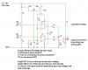
Here is a basic adjustable shunt load voltage regulator circuit.
By adjusting the on and off voltages it will be possible to set the load bank to cycle full on at a high point voltage but not disconect until a lower voltage is reached.
")
I also posted a cheap but efective way to make load resistors in the **** chat area under Dumpster diver tips and tricks.
This should give you a basic but simple and reliable way to regulate your voltage with a load.