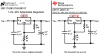
Continue to Site

Welcome to our site!

Electro Tech is an online community (with over 170,000 members) who enjoy talking about and building electronic circuits, projects and gadgets. To participate you need to register. Registration is free. Click here to register now.

  • Welcome to our site! Electro Tech is an online community (with over 170,000 members) who enjoy talking about and building electronic circuits, projects and gadgets. To participate you need to register. Registration is free. Click here to register now.

regulator 37v to down volt

Status
Not open for further replies.
Have you built it using exactly the components shown? If so, the voltage should be adjustable all the way down to 1.2V.
 
what values for R1,R2? Vout = 1.25V (1 + (R2/R1)) + I adj R
Also Pd=(Vin-Vout)*Iout
Then Tj rises with heatsink, Rca, thermal resistance
so total rise in Tj=( Rjc+Rca)*Pd

for (j)unction, (c)ase, (a)mbient, (d)issipation
 
Check the pin connections, again. Note that the TO220 tab is the output terminal, so has to be isolated from the heatsink. And yes, you likely will need a heatsink if drawing more than a few tens of mA load current.

Attached below is where Circuits Today stole their info (pretty bad web site, IMHO), but left half of it out....

317.png


The full data sheet can be downloaded from here.
 
Last edited:
The datasheet shows that a 240 ohm resistor can be used with the more expensive LM117 but the LM317 needs no more than 120 ohms if it has no load.
 
what values for R1,R2? Vout = 1.25V (1 + (R2/R1)) + I adj R
Also Pd=(Vin-Vout)*Iout
Then Tj rises with heatsink, Rca, thermal resistance
so total rise in Tj=( Rjc+Rca)*Pd

Hi Tony thanks for you help but this math is a bit complicated to me

for (j)unction, (c)ase, (a)mbient, (d)issipation
Check the pin connections, again. Note that the TO220 tab is the output terminal, so has to be isolated from the heatsink. And yes, you likely will need a heatsink if drawing more than a few tens of mA load current.

Attached below is where Circuits Today stole their info (pretty bad web site, IMHO), but left half of it out....

View attachment 101129

The full data sheet can be downloaded from here.

Mike do you think that the circuit I posted is faulty? Maybe the one you posted is right?

The datasheet shows that a 240 ohm resistor can be used with the more expensive LM117 but the LM317 needs no more than 120 ohms if it has no load.
Audioguru I did 240ohms as on circuit.
 
Audioguru I did 240ohms as on circuit.
ST Micro did not invent the LM317, instead they simply copied it from National Semi. Both of them say in their datasheets that there is a minimum load current but ST Micro neglects it. The minimum load for an LM317 is 10mA but the 1.25V reference in the 240 ohm resistor makes a current of only 1/25V/240 ohms= 5.2mA so some LM317 devices will not work properly and cause their output voltage to rise when there is no other load and the supply voltage is high. You are simply lucky that your LM317 needs only 5.2mA or less, or that your load current is always at least 5mA.
 
ST Micro did not invent the LM317, instead they simply copied it from National Semi. Both of them say in their datasheets that there is a minimum load current but ST Micro neglects it. The minimum load for an LM317 is 10mA but the 1.25V reference in the 240 ohm resistor makes a current of only 1/25V/240 ohms= 5.2mA so some LM317 devices will not work properly and cause their output voltage to rise when there is no other load and the supply voltage is high. You are simply lucky that your LM317 needs only 5.2mA or less, or that your load current is always at least 5mA.
Load current have to be more cause I am going to use this circuit to charge lithium batteries. I settle output voltage so that lithium batts don't get over charge.
 
I did this especially for audioguru ...

This simulation shows a (TI) LM317 loaded only by its voltage feedback network (R1 and R2, when R3=1GΩ) as the Red trace, and when R3=100Ω (so that the LM317 load current is >140mA) as the Green trace.

I step the resistors R1 and R2 in the voltage feedback network so that R1/R2 = 0.1 = constant, so that I show what happens to the output voltage V(out) as R1 steps from 60Ω all the way to 1200Ω with corresponding changes in R2 to theoretically keep V(out) constant.

Now, Audioguru blathers on about dire things happening if R1 is 240Ω instead of 120Ω, but you can clearly see that almost nothing is happening to the output voltage, with the load current = zero, until R1 exceeds 600Ω. Note that if the load current is ~140mA, when R3=100, then V(out) is well behaved even if R1 is much higher than 240Ω.

I have routinely used R1=240Ω or even higher values in circuits I built and have never seen the output voltage higher than predicted by the R1/R2 ratio, considering the resistor and LM317 tolerances...

I think AudioGuru is making a mountain out of a molehill!

317vr.png
 
I did this especially for audioguru ...
This simulation.....
The model is for a "typical" device that has a lower minimum load current than one that is not as good but still meets the spec's. Is the model accurate?

I think AudioGuru is making a mountain out of a molehill!
It is explained on the datasheets. Maybe the manufacturers scare people with the minimum 10mA load current spec hoping that they buy the more expensive LM117 so they can use 240 ohms.
Maybe you build an LM317 power supply using 240 ohms with an LM317 that actually works with a low minimum load current then you need to replace it but the replacement needs 120 ohms. The output voltage will rise and zap a low current Cmos circuit you are testing.
 
The model is for a "typical" device that has a lower minimum load current than one that is not as good but still meets the spec's. Is the model accurate?


It is explained on the datasheets. Maybe the manufacturers scare people with the minimum 10mA load current spec hoping that they buy the more expensive LM117 so they can use 240 ohms.
Maybe you build an LM317 power supply using 240 ohms with an LM317 that actually works with a low minimum load current then you need to replace it but the replacement needs 120 ohms. The output voltage will rise and zap a low current Cmos circuit you are testing.

Audio you're saying if I change 240ohm resistor to 120ohm would produce more output voltage?
 
Audio you're saying if I change 240ohm resistor to 120ohm would produce more output voltage?
Audioguru might say it, but that is not the root cause of your problem...
 
Audio you're saying if I change 240ohm resistor to 120ohm would produce more output voltage?
With 240 ohms then all expensive LM117 ICs work perfectly but some LM317 cheaper ICs have the output voltage rise when the load current is low, as it says in the datasheets. The output voltage rises higher than you have it set to. Then when you load it the voltage drops down to what it should be. Then there is terrible voltage regulation. If the resistor is 120 ohms for an LM317 the voltage regulation is excellent.

Copy-cat manufacturers make mistakes sometimes, you know. National Semi invented the LM117 and LM317 and correctly shows 240 ohms for the more expensive LM117 in their datasheet. Texas Instruments copied it but changed the correct LM117 to a wrong LM317.
 

Attachments

  • LM317.png
    LM317.png
    58.4 KB · Views: 144
Andrew Borg:

You seem to have missed a key point. If R2 is adjustable (i.e. a pot or rheostat), then V(out) is adjustable from 1.25V to about 3V less than the unregulated input voltage. For example, in the following simulation, V(out) is controlled by R2 as R2 sweeps from 1Ω to 5kΩ.

317vr1.png
 
Last edited:
Suppose you make the regulator adjustable as I show in post #16 and add a 50Ω load resistor. I repeat the sim to plot the voltage into the reg V(in)=blue, the output voltage V(out)=violet, the current into the reg Ix(U2:IN)=green, the current in the load resistor I(R3)=yellow, and the power dissipation in Watts in the regulator (red expression and red trace), all as a function of R2.

Note that to get rid of ~7W of heat-producing power in the reg, it will have to be mounted on a large heat sink. You will have to confirm how big the heat sink needs to be based on the load that you connect to the output of the regulator. Also, the power dissipation would be less if you reduce V(in).

317vr2.png
 
Last edited:
One thing that it has always worked for me when troubleshooting LM317 circuits, is to measure the voltage between the OUT and ADJ pins.
It should be 1.25 volts +/- a few dozen millivolts (look for yourself the actual values in the datasheet).
This at least will tell you whether the device is operating within its linear range. Also if you have a defective device.

This last instance happened to me when I purchased a grab pack from e-bay. Something like 15 regulators for only $1 US. Of course, for a few of those the voltage was out of spec.
 
Sorry guys for the trouble today I noticed that I connected the Lm317 pins wrongly .
It's working fine now down to 1.25v.
Thanks for your help.
 
Status
Not open for further replies.

Latest threads

New Articles From Microcontroller Tips

Back
Top