Continue to Site

Welcome to our site!

Electro Tech is an online community (with over 170,000 members) who enjoy talking about and building electronic circuits, projects and gadgets. To participate you need to register. Registration is free. Click here to register now.

  • Welcome to our site! Electro Tech is an online community (with over 170,000 members) who enjoy talking about and building electronic circuits, projects and gadgets. To participate you need to register. Registration is free. Click here to register now.

redesign help diagram plz help

Status
Not open for further replies.

mail866

New Member
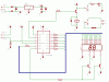
i want to modify this circuit to fuction for the fridge so it should work like a digital theromoter swtich connected to fridge compressor so it that will monitor a refrigerated room. it should effectively turn off the compressor of the fridge when the temperature is lower or equal to -5 degree Celsius and it will turn it back on when temperature is greater than -5 degrees Celsius. It should also give sound warning signal when temperature exceeds the 0 degree Celsius.

plz can somebody help in telling me what compents should be replaced here. for the new diagran according to the new requirments.
 

Attachments

  • picthermometerthermostat_1266693107.gif
    picthermometerthermostat_1266693107.gif
    34.4 KB · Views: 282
Last edited:
the modifications required to do what you ask are done using the code that is stored in the pic
 
The circuit will not work properly because you have connected the bases of the two buffer transistors together.
 
Last edited:
hanks a lo. plz how can i fix this? and second sir can u tell me about new pic and tempersure sensor parts name to be replaced instead here in order for i o be more efficen and reliable. more better components.
 
This circuit is off two ways:
- D2 unnecessary. D3 is enough for reverse power input protection.
- Need two I/O pins to control T2 and T3, not one pin driving both transistors. You have to be able to turn the segment displays on one at a time, in a multiplex fashion.
The first can maybe be ignored, the second defeats the display. Problem: If you can't/don't reassign MCLR to be an I/O pin and thus gain another I/O pin to drive the second transistor, this PIC won't work for this design. You'll have to use a PIC with more I/O pins.

As for changing the code, we need the language you are using and the actual code you have (written?) so far. Even then no one may be able to help you with the code.
And we need to know which temperature sensor you are using to figure what values it puts out at the temperatures you mention.
Good luck with your project.
kenjj
 
Status
Not open for further replies.

Latest threads

New Articles From Microcontroller Tips

Back
Top