Continue to Site

Welcome to our site!

Electro Tech is an online community (with over 170,000 members) who enjoy talking about and building electronic circuits, projects and gadgets. To participate you need to register. Registration is free. Click here to register now.

  • Welcome to our site! Electro Tech is an online community (with over 170,000 members) who enjoy talking about and building electronic circuits, projects and gadgets. To participate you need to register. Registration is free. Click here to register now.

Rebuilding My Power Supply

Status
Not open for further replies.

kinarfi

Well-Known Member
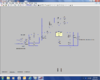
I have a variable power supply that had some problems, so i'm rebuilding it, the transformer is good for over 20 amps and 24 volts DC and there are several occasions where I need all 20 amps. I have it mind to go linear again, but I'm hoping someone has some ideas that are better than mine. The attached design is basically what I had before except I plan to put a switch on it this time which will double the output voltage, from 24 to 48.
I have a couple of massive NPNs (5/16" fine thread stud) (that I haven't blown up yet, I've tried to get the data sheets, but can't find them), that I plan to use for the output xistor. I also have a bunch of IRF4905 and IRF3205 FETS and lots of heat sinks and fans plus a bunch of inductors, 33uh -47 uh & others that are power inductors and other stuff stripped out of power supplies. If I knew how to make them variable, that's the way I would go, but I have already disassembled them. NPN#163H72 8025 I think there is a Westing House symbol on it
Thanks,
Kinarfi
 

Attachments

  • pwr supply.png
    pwr supply.png
    29.4 KB · Views: 1,212
  • Snapshot_20131220.JPG
    Snapshot_20131220.JPG
    24.1 KB · Views: 624
Last edited:
I doubt that the massive output transistor has current gain at 20A higher than 15. Then the 2N4403 will blow up with a current of 1.3A.
Wait a minute. The 2N4403 will probably melt before it blows up.
 
i will watch this with interest! 20A!!!!! nice one, Could you lend it to billy? It might help him find some of those shorts ;)
 
Oh what little faith we have, got any ideas that will help or you just gonna watch the horizon for smoke, if so,at least fill your bucket with water, so you can put me out :)
 
We are routing for you honest! Only suggestion from me is go the fet route. I would be looking out for schematics for big supplies and see how they do it. Thats one chunk beast, i would love it! Dad has an old arc welder with a big transformer in :D, ONE DAY that is going to be my lab supply :D:D
 
Oh what little faith we have, got any ideas that will help or you just gonna watch the horizon for smoke, if so,at least fill your bucket with water, so you can put me out :)
We don't design circuits with FAITH. We use the maximum allowed spec's in the datasheet then use maybe 80% of them so the parts last for a long time.
You NEED the datasheet for the massive transistor you are planning to use so you can use a suitable driver transistor and heatsink for it.
 
K,
Play with this for a while and see what you think.
If you don't have a 317 model I think there are some 3 terminal regulators in the power library that would work.
Just from my look I would say 24 volts out will be a stretch and if you bridge it make sure to use a 317HV .
Good luck!
PS I see some transistors similar to yours rated at 200 watts.
PSS. Keep the faith
 

Attachments

  • Ks sup.png
    Ks sup.png
    129.2 KB · Views: 523
  • K's supply.asc
    4.4 KB · Views: 352
Thanks Ron, that's close to what I started with, but due to the desire to use a ten turn 10k pot with dial face, I'm kind of stuck with the 10K pot. So far, the massive transistor(163) has handled the current with no problems, but the ripple gets nasty as the voltage and current go up, but I expected that. I get just a hair more than 24 vdc from the bridge and the 10,000 uF cap and on one experiment I did, if fed the base of the 163 with my other power supply and used a 1 ohm load and at 18v to the base, I had 16+ volts out at 15.8 amps and ~3-4volt ripple. At lower voltages around 13 and lower, I'm pretty sure I'll get real close to 20 amps out and a lot smoother. I'll hafta take a photo when I get done.

I was hoping to to use a buck switch mode system, still looking into that, but the high amperage my stop me.
 

Attachments

  • pwr supply#2.png
    pwr supply#2.png
    33.3 KB · Views: 605
  • POWER SUPPLY.asc
    4 KB · Views: 346
Your new power supply circuit must have horrible voltage regulation because the emitter-follower transistors are not within the negative feedback loop of the LM317. You can set the output of the LM317 to +12.0V and the output of the emitter-followers will be about +11V with a low current load. But the output of the emitter-followers will be about +9V when the load current is 16A.

R1 provides a load for the LM317 when the entire project has no load but R1 does not have much current when the output voltage is low.
The datasheet for the LM317 says that R3 in your circuit should be no higher than 240 ohms for the more expensive LM117 and no higher than 120 ohms for the LM317 to prevent the output voltage rising when the load current is low. The current in R3 will always be the same at any output voltage. Then R3 provides the minimum required load current for the LM317, not R1. All schematics in the datasheet show 240 ohms and the LM117.
If you reduce the value of R3 then you also must reduce the value of the pot.
 
Kinarfi,

You would do well to read this book from the folks who wrote it. http://cp.literature.agilent.com/litweb/pdf/5989-6288EN.pdf Look especially at Fig. 15 where it shows how to use a big power resistor to take all the hell when the linear power supply is asked to supply high current at low voltage. I used this circuit 40 years ago and it works fine.
036.JPG
Can you see where I did something wrong with the placement of components?

Ratch
 
Last edited:
POWER SUPPLY#1.png
Pretty much finish, just gotta put the housing back together and maybe add the negative half to it, guess I could even make it controllable, but I don't really need it, so why bother. Used Ron's design with a few slight variations. Max output is 20.7V open circuit. Max current 19.7 amps@15.6 volts, I think, didn't write it all down, will do a better job of writing it down tomorrow. Appears to be very stable and smooth.
 

Attachments

  • 20131223_180642.jpg
    20131223_180642.jpg
    452.1 KB · Views: 467
I have a big old supply that can chuck out loads of amps, I dont use it except when the car wont start, a couple of times it vaporised circuits it was powering, due to lask of current limit.
Current limit is really required for a heavy psu, to protect not only the circuit being powered but the psu itself.
 
Hi,

If you are using Power Supply #2 then you should note that it is not really regulated. It is partially regulated but the feedback does not come from the very output so the output will vary with temperature and current.

To get it to regulate better in that exact configuration (which may not be the best to start with though) you could add a differential amplifier that would compensate for the transistor base emitter drops and any current share resistor drops. If you are interested i'll post a drawing.

You could vary the adjustment to make up for the loss too, but you may find that you have to keep adjusting it often.

Also, the transistors may need base currents of 1 amp each to get 20 amps out if they are paralleled. That means the driver transistor has to be able to handle 2 amps, or use more than one driver transistor.
 
I have a big old supply that can chuck out loads of amps, I dont use it except when the car wont start, a couple of times it vaporised circuits it was powering, due to lask of current limit.
Current limit is really required for a heavy psu, to protect not only the circuit being powered but the psu itself.
I know what what you mean, while I was messing with it, I discharged the caps by shorting the the out put and it took out the PNP emitter and the 4.7 resistor, it still looked good and caused me some grief for a while, It had changed from 4.7 to a Megohm or so, OR, the short took out the resistor and then the emitter.
Oh well, it's fixed now and I plan to put an inductor in the out put which may slow the spikes down. Also added a capacitor to the NEG side, but when I add a load to it, there is lots of ripple, So I plan to add a LM337 with an emitter follower to it to get rid of a lot of the ripple.
 

Attachments

  • POWER SUPPLY#1B.png
    POWER SUPPLY#1B.png
    31.3 KB · Views: 888
Hi,

If you are using Power Supply #2 then you should note that it is not really regulated. It is partially regulated but the feedback does not come from the very output so the output will vary with temperature and current.

To get it to regulate better in that exact configuration (which may not be the best to start with though) you could add a differential amplifier that would compensate for the transistor base emitter drops and any current share resistor drops. If you are interested i'll post a drawing.

You could vary the adjustment to make up for the loss too, but you may find that you have to keep adjusting it often.

Also, the transistors may need base currents of 1 amp each to get 20 amps out if they are paralleled. That means the driver transistor has to be able to handle 2 amps, or use more than one driver transistor.
I'm not using #2, I'll be using #1B, but I would like to to see you're drawing, especially if you have it as a .asc . Note the use of a single 163H72 output transistor which I thank came from my days at Hughes Air Craft 20 years ago and it seems to handle 20+ amps with out a wimper, sure wish I could find the actual specs on it.
 
The LM350 needs 10mA minimum load current or some of them will raise their output voltage without a load. The 10mA is usually provided by using a 120 ohm resistor from the output to the ADJ pin but your circuit has 500 ohms which is too high.
If the resistor is changed then the value of the pot must also be changed.

You have backwards polarity on the red LED.
 
I'm not using #2, I'll be using #1B, but I would like to to see you're drawing, especially if you have it as a .asc . Note the use of a single 163H72 output transistor which I thank came from my days at Hughes Air Craft 20 years ago and it seems to handle 20+ amps with out a wimper, sure wish I could find the actual specs on it.

Hi,

Ok good. Your negative regulator looks like it lacks true regulation also though, you might check that.

Yes that kind of transistor was used a long time ago, not sure if they are used anymore though. The rating is probably pretty high, but they were not exceptionally high speed transistors as compared to today's devices anyway. Maybe they used them in a 400Hz converter or something, did you work on any 400Hz converters?

The additional circuitry i was going to suggest for circuit #2 was going to be a differential amplifier connected with inputs across the two transistor base emitters so that it would be measuring the voltage drop across both base emitter diodes as well as any current sharing resistors you might add. The output goes to the BOTTOM of the lower resistor used to set the voltage of the LM317. That way any voltage that is deducted from the LM317 output via the base emitter diodes gets added right back to the reference circuit so the voltage gets boosted right back up, meaning the output comes up true to the original LM317 circuit without any transistors. So for example if you had a normal LM317 with no transistors and the output was set to exactly 5v, after adding the transistors the output would drop to maybe 3 volts, then after adding the differential amplifier the output would go back up to exactly 5v but now the transistors would be handling all the current.
There is a drawback though and that is because the two transistors work as emitter followers that means there is plenty of drop in the emitter base diodes and sometimes that's a lot with circuits like this because that limits the maximum output voltage. But if you are still interested anyway i'll show the circuit, which requires an additional op amp to make it work (one section of an op amp) and four resistors.
 
The LM350 needs 10mA minimum load current or some of them will raise their output voltage without a load. The 10mA is usually provided by using a 120 ohm resistor from the output to the ADJ pin but your circuit has 500 ohms which is too high.
If the resistor is changed then the value of the pot must also be changed.

You have backwards polarity on the red LED.

The data sheet states that Adjustment Pin Current is typically 50 and max 100 micro Amps. 1.25 / 100 micro amps = 12.5K, so 500 is well within the operating area. 120 and 240 ohms are convenient standards, but not the rule, IMO. I don't suppose you would believe I have a very rare zener LED would you? No? OK you're right, It's drawn in backwards, Thanks.
EDIT I see you strongly believe in 120 ohms for R1, Think you'll ever change your mind and accept that it can be something else? https://www.electro-tech-online.com/threads/lm317-calculating.119697/

Yes, I did a little work with 400Hz inverters, the theory behind 400 Hz is quite interesting, if I remember right, the ideal frequency for motors is 380 Hz, so they rounded it up to 400 Hz, a motor running at 400 Hz can produce 3 time the HP of the same size and weight motor running at 60 Hz.

The negative side won't get used much and just reducing the ripple will be ok for what I do. I will probably just set the voltage around 16 and forget about it.
 
Last edited:
And I thought aircraft used 400hz because it was the speed at which the engine turned the alty!
I have a power supply I built and robbed bits of other designs that actually uses a led as a zener, but its forward biased, its part of a current source, its used to dump current into a current limit pin of a regulator chip to reduce current limit, it can go all the way down to 0, would probably have worked better with 2 trannys and a resistor.
 
Status
Not open for further replies.

Latest threads

New Articles From Microcontroller Tips

Back
Top