Let me start off by saying Hello!! I have just gotten into messing with electronics. I realized this is a skill I have to develop because I am a guitar player who is sick of paying for repairs and modifications.
To kind of get myself started, I've designed a project for myself. I want to install LED lights into my guitar, so that as I play, they play along with me. I pick/strum, they light up. This is a very cool effect. Here is a perfect example of what I want to do. YouTube - My Custom LED Guitar - One of a kind!
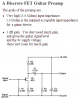
I have been able to find schematics. I've been able to create them to the point of working. However, they aren't working properly.
I think I'm having trouble because I don't know what to use. I know I want 8 blue LED's. But I don't know what resistors to get or what kind of power supply to use (obviously a battery, I just don't know what will work). Any, and I mean ANY help will be appreciated.
This is one of those things where I'm confused now, but after I do it, things will make much more sense.
To kind of get myself started, I've designed a project for myself. I want to install LED lights into my guitar, so that as I play, they play along with me. I pick/strum, they light up. This is a very cool effect. Here is a perfect example of what I want to do. YouTube - My Custom LED Guitar - One of a kind!
I have been able to find schematics. I've been able to create them to the point of working. However, they aren't working properly.
I think I'm having trouble because I don't know what to use. I know I want 8 blue LED's. But I don't know what resistors to get or what kind of power supply to use (obviously a battery, I just don't know what will work). Any, and I mean ANY help will be appreciated.
This is one of those things where I'm confused now, but after I do it, things will make much more sense.