Continue to Site

Welcome to our site!

Electro Tech is an online community (with over 170,000 members) who enjoy talking about and building electronic circuits, projects and gadgets. To participate you need to register. Registration is free. Click here to register now.

  • Welcome to our site! Electro Tech is an online community (with over 170,000 members) who enjoy talking about and building electronic circuits, projects and gadgets. To participate you need to register. Registration is free. Click here to register now.

Reading a voltage when there are ground drops?

Status
Not open for further replies.

Flyback

Well-Known Member
Hi,
Do you know of a lower component count solution for the following?...
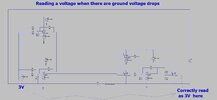
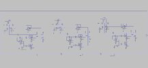
As you can see, there is a Diff Amp which reads a 3V source voltage…..then passes it to circuitry which is grounded to a slightly different potential….and that circuitry there must read the 3V voltage correctly.
The attached does it but is too high in component count. Do you know of a lower component count way?
 

Attachments

  • Diff Amp for when there are ground drops.asc
    7.3 KB · Views: 176
  • Diff Amp for when there are ground drops.jpg
    Diff Amp for when there are ground drops.jpg
    135.9 KB · Views: 197
Is there a reason why you felt that a simple, single stage diff amp would't work?

That's what I've modeled in the attached circuit.
Note: I've also change the 3V source to be a 200mV saw tooth centered about 3V, and ramped the current to see that it works over varying conditions.
 

Attachments

  • Diff Amp for when there are ground drops CP58.asc
    2.5 KB · Views: 168
Are you planning on using an A/D to read the voltage ?

If so many now available with differential input stage, including processors
with onchip A/D's.

What is the accuracy, resolution you want for the measurement ? Diff stages
built out of discrete OpAmps and resistors have issues in resistor accuracy
affecting common mode rejection. Instrumentation Amplifiers solve that
using laser trimmed diff amps that are done during production.


Regards, Dana.
 
Thanks, the idea is to actually make a UC3902 out of separate blocks. So we need a differential "share" bus....thats why this is needed

UC3902

The '3902 is a device which passes a "share" bus between paralleled power supplies, so that they can use that voltage to trim their output current, so that all PSUs share the total output current.....the "share" bus must be a differential bus, since at each power supply, the ground is slightly different in potential.

The actual "share" bus voltage is simply the voltage output of the current sense amplifier, of the PSU that is shipping the most current out of all PSU's.

We cant use the '3902 because its gain is fixed at 40...and it uses a fixed offset voltage of 35mV....and we may need it to be higher than this.
 
So we need a differential "share" bus....thats why this is needed

That is a totally different situation.
To start with, the drivers to the common bus must be either current controlled, or the bus drive connections all via equal resistances to balance them and limit current. Presumably the bus voltage should be the mean of all individual devices on it?

It cannot be simple voltage from opamps as you have shown, otherwise some drivers will be overloaded and the output unpredictable.


OK; Looking at the UC3902, its a different configuration again:

The only drive out is via a diode to bus positive, so there is no contention. That just drives the bus with a voltage proportional to current, so whichever supply has the highest load is the one driving via its diode.

That will have some 0-100% load scaling, apparently 10V if the supply voltage permits, and all devices use the voltage read back to set the percentage of individual maximum current they provide.

The bus negative is not active or driven in any way, it's purely a shared ground reference for the differential amps.

The whole lot uses two, four-resistor differential amps (plus a diode) for all that.
The rest of the device is for the load percentage control.
 
Sure looks like simple solution, plus you get good cmr thru onboard
diff amp.

For the UC3902 to work properly, the modular power system has to consist of power supplies which possess their own feedback circuits. Furthermore, the stand alone modules have to be equipped with true remote sense capability or with an output voltage adjustment terminal. Each module must have its own load share controller. The operating principle of a load share mechanism is to measure the output current of each individual module and to be able to modify the output voltage of the units until all participating power supplies deliver equal output currents. It is accomplished by the UC3902 integrated circuits which are connected to the common load share bus and adjust the positive sense voltage (or the voltage of the output voltage adjust pin) of their respective modules to provide equal load current sharing.

1665063805257.png


Regards, Dana.
 
Last edited:
Another method, single chip :

1665066486794.png


This can be done I think w/o CPU intervention as well. Also most chip resources
available for other tasks.....see right hand window resources used/left.

Whats on this chip, multiple copies in many cases :

1665066787088.png


If you use the onchip DelSig and Analog Mux facilities you can configure the effective gain
as seen by the ADC.

If the DAC range, 0 - 4V not exact fit you can use the onchip OpAmps in PGA configuration
to scale that as well.

Note I added sequencer in case you need to have controlled startup of various supplies, thats
also onchip.


Regards, Dana.
 
Last edited:
The whole lot uses two, four-resistor differential amps (plus a diode) for all that.
Thanks, yes, i tried to copy what they've done, with their two diff amps, but it didnt work.

As you kindly suggest, I need to add an ideal diode to the cct in the top post, but the component count is getting very high.....I believe their (ti.com) block diagram of uc3902 is purely indicative.....they must be using an ideal diode cct rather than the simple diode they show.
 
A-ha, Thankyou RJenkins, you were correct, the UC3902 diff amp method does actually work...when i tried it before, i stupidly didnt have the opamp power rails high enough in voltage and i was thus getting saturation of signal near the rails......so the attached shows the differential share bus being correctly received by all three positions.......i am a little concerned though, that , as RJenkins kindly says, the negative of the diff share bus is not actually driven...its floaty......i prefer a driven bus line , since its better for noise immunity.
 

Attachments

  • Diff Amp a la UC3902 _multiple.asc
    14.9 KB · Views: 170
  • Diff Amps a la UC3902.jpg
    Diff Amps a la UC3902.jpg
    122.1 KB · Views: 167
the negative of the diff share bus is not actually driven...its floaty
It does not float! Read the data sheet.
It is supposed to have a single-point ground / 0V connection somewhere in the system. That minimises current on it, so minimises any differences in reference voltage along it.

If you drive it at each point, that's where you can introduce errors.

Neither do you need "ideal diodes" as you mentioned earlier - it's a form of precision rectifier circuit, where the opamp compensates for diode drop, as its feedback is taken after the diode. Just normal signal diodes.

You circuit is still crazy; you only need two opamps in each unit!!!
 
You circuit is still crazy; you only need two opamps in each unit!!!
..Thanks, i just dont seem to be able to get rid of the other op amps...

..The attached (LTspice and pdf) is the use of all this....ie, 3 paralleled linear regaultors with the differential "share" bus......it handles the case when the ground at each linear regular is different to the others.
 

Attachments

  • Parallel linear regulators with load share _221009.pdf
    224.7 KB · Views: 171
  • Pllel Linear regs with Load share_221009.asc
    48.6 KB · Views: 162
Last edited:
You circuit is still crazy; you only need two opamps in each unit!!!
Thanks, here i have removed the opamps...and this doesnt now work...the "share" bus isnt holding at the highest voltage which is 3V.
 

Attachments

  • Diff Amp a la UC3902 _LESS OPAMPS.asc
    11.2 KB · Views: 154
  • Diff amp share bus _Less opamps.pdf
    160.9 KB · Views: 165
You do not appear to have the ground point on share-
It must connect to some system ground at a single point, as already stated.

Also - are you getting us to help you cheat with a thesis project or something like that??
"SMPS Course" in the PDF????

Flyback-1.png
 
Thanks, thats my SMPS course that i wrote years ago...if you want i can send it to anyone who wants the google drive link?
You do not appear to have the ground point on share-
The share bus is pulled down to local ground by a 1k resistor at each linear regulator, which i thought was enough?
 
Thanks, "Share+" is x volts above "share-"......where x is the voltage at the output of the current sense amplifier of the stage thats shipping the most current.....i see what you mean though...on page 9
of the App note the share- is indeed connected to output gnd in one place...
I am not sure why it has to be so?..........After all, as long as you can put the currnt sense max voltage on the share bus, and then get it back off again, then i dont see why it has to have the single point ground connection?

UC3902 App note.
 
Last edited:
Status
Not open for further replies.

Latest threads

New Articles From Microcontroller Tips

Back
Top