Continue to Site

Welcome to our site!

Electro Tech is an online community (with over 170,000 members) who enjoy talking about and building electronic circuits, projects and gadgets. To participate you need to register. Registration is free. Click here to register now.

  • Welcome to our site! Electro Tech is an online community (with over 170,000 members) who enjoy talking about and building electronic circuits, projects and gadgets. To participate you need to register. Registration is free. Click here to register now.

Reading 5A with a 500mA moving coil meter?

Status
Not open for further replies.

bigal_scorpio

Active Member
Hi to all,

Just having one of my stupid days and can't remember how I used to change the scale of meters to suit the range of measurement.

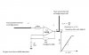
The meter I have is a small moving coil one with a scale of 0 to 500mA but the load I need to measure is between 1 and 5A. I seem to remember that I need to put another resistance in parallel with the coil to take the lions share of the current but therein lies the problem. If I am correct in thinking the new resistance would need to be roughly 1 tenth of the original coil resistance then I will be stuck since the coil seems to measure around .5r then I would need a resistor of 0.05r. If so then I have nothing so small.

Have I got this right? Also it would help to have a little adjustment available to calibrate the meter, but again if my values are correct I am struggling to find anything small enough.

Al
 
Yes, you will need a shunt resistor that drops a voltage equal to the resistance of the meter when the resistor is carrying 4.5A. The easiest way to determine the meter resistance is to run 500mA through it and measure the voltage drop across the meter.

For calibration you can buy a shunt resistor slight larger than required and put a small variable resistance between the external resistor and the meter.
 
Cruts means slightly larger as in higher resistance not higher current.
(a higher current shunt would be lower in resistance)
 
Yes, I meant a larger (higher) resistance shunt.
 
Hi Guys,

Thanks for all the input.

I have made through experimentation a wound resistor that gives me full scale deflection at 5A, after only a few failures.

I just wish someone would come up with a bridge type device with a pic doing the maths and giving a readout on an LCD.

That would be a project worth building, well for me anyway. I would love to be able to measure sub ohm resistances easily and with some accuracy as quite a few of my projects lately seem to require tiny value resistors!

Al
 
They have, do a google for lock in milliohmeter.

I looked at it but decided to do it using a 1a current source.
 
Hi to all,

So I went ahead and built a bridge and it works really well. I am using my DMM to read the results and it is pretty accurate but now I have got the bug to make it a standalone meter. I have made voltmeters with Pic Micro's before and had success with them but they were all designed to measure either 5v or more.

My problem is that I can't figure out how to use the Pic to read Millivolts. I know I could simply read the bridge with the Pic using the standard 0 to 5v scale but that would only give me a resolution of almost 5mV per notch, which on small readings would give poor readings.

I wondered about boosting the voltage with an op amp but in the past I have only had limited dealings with them and not always been successful. So if anyone has a better idea on how to do this or if its the only way then a bit of advice on which op amp and the basics of how to accomplish it.

Thanks in advance, Al
 
You answered the question, use an op amp, if your amplifying the output of a wheatsone bridge or accross a sense resistor then configure an opamp such as a ca3130 or lmc660 or similar as a differential amp and connect it to the bridge, there are several examples on the net.

A gain of a 100 would give 50uV per count.

Look at my recent thread for building a psu with a pic showing v and a, the last schematic allthough naff and hand drawn shows 1/2 an lm358 at the bottom right, this is a differential amp that amplifies the v drop accross the sense resistor, this setup gives 5v for 1a, scaling the resistors would give you the right o/p, the lm358 goes straight into the pic and works great.

https://www.electro-tech-online.com/threads/adding-a-current-limit-led-to-my-lm723-bench-psu.131608/
 
Last edited:
Hi again guys,

Well I have done what I thought was right and built an op amp circuit. I actually did the one for a none inverting dc amplifier from the LM358 datasheet.

When connected to my bridge I get strange readings from the output of the op amp. My bridge is a 1A one and when I check its output with a 0r47 resistor the DMM across the bridge output shows .47v when I check this against the output of the op amp I expected to see 100x0.47v or 4.7v but I got 5.35v instead! I then thought that the output may be better with less gain and changed the gain resistor of the op amp from 1M to 100k which I thought may be better in the long run as I would then have a bigger scale that I could test with the circuit, as in fro 0 to 50r instead of 0 to 5r. But the results were similar only obviously smaller with the r47 giving .53v at the op amps output.

A little about the bridge circuit and op amp. I am powering both from a SLA 12v battery for test purposes ( I wondered if this was enough headroom for the op amp?)

I intend still to use a PIC12F628a or similar as a voltmeter with an LCD display and build it all into the same box for convenience sake.

Can anyone suggest where I'm going wrong here?

Help appreciated, Al

PS I have checked and rechecked the circuit and it is exactly the same as the one posted below.
 

Attachments

  • Opamp1.jpg
    Opamp1.jpg
    43.2 KB · Views: 194
I think thats a little too high a fb resistor, you'd be better with a 1k and a 100k, or as you say reduce the gain to 10.
Also is the ground side of r1 a proper ground, ie its not subject to volts drop caused by the load.
The lm358 can go to almost ground, but needs around 2v or so clear of vdd.
If you want to go rail to rail an lmc660 is worth considering, there is a single version too.
 
Status
Not open for further replies.

New Articles From Microcontroller Tips

Back
Top