Hi,
This is a further consolidation of my previous posts which hopefully draws my questions to a final solution.
I have a highly inductive AC source, a dynamo which varies in frequency and voltage. System efficiency is imperative and so is power extraction. To that end, maximum extraction can be had by switching in capacitance at various points in the frequency.
By implementing active rectification I had hoped to be able to switch in the capacitance at the DC side via an N-fet low side. The bridge FET's (unlike an ideal diode) don't prevent the reverse flow so I theorised it would be cutting down components and complexity. A win win. This assumed capacitance could be added in parallel to have the same effect as in series.
LTspice seemed to agree. Frequency sweeps over various capacitance show the change in power.

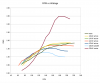
So, I prototyped it and ran some real-life tests. The "none" shows the base-line. "230uF series" shows the ideal extraction (it would fall pretty rapidly if the frequency were any higher but then a smaller cap would switch in).
Clearly whether the capacitance is in series or parallel has a much greater difference than I expected, and while the active rectification based switch in does work it's no where near as performant.
Can anyone explain why LTSpice has got it wrong and/or why the results are as they are?
Cheers,
Andrew
This is a further consolidation of my previous posts which hopefully draws my questions to a final solution.
I have a highly inductive AC source, a dynamo which varies in frequency and voltage. System efficiency is imperative and so is power extraction. To that end, maximum extraction can be had by switching in capacitance at various points in the frequency.
By implementing active rectification I had hoped to be able to switch in the capacitance at the DC side via an N-fet low side. The bridge FET's (unlike an ideal diode) don't prevent the reverse flow so I theorised it would be cutting down components and complexity. A win win. This assumed capacitance could be added in parallel to have the same effect as in series.
LTspice seemed to agree. Frequency sweeps over various capacitance show the change in power.
So, I prototyped it and ran some real-life tests. The "none" shows the base-line. "230uF series" shows the ideal extraction (it would fall pretty rapidly if the frequency were any higher but then a smaller cap would switch in).
Clearly whether the capacitance is in series or parallel has a much greater difference than I expected, and while the active rectification based switch in does work it's no where near as performant.
Can anyone explain why LTSpice has got it wrong and/or why the results are as they are?
Cheers,
Andrew
 Your post #1 sim doesn't have a cap either in series or in parallel with the inductor.