Continue to Site

Welcome to our site!

Electro Tech is an online community (with over 170,000 members) who enjoy talking about and building electronic circuits, projects and gadgets. To participate you need to register. Registration is free. Click here to register now.

  • Welcome to our site! Electro Tech is an online community (with over 170,000 members) who enjoy talking about and building electronic circuits, projects and gadgets. To participate you need to register. Registration is free. Click here to register now.

Rcd-1

Status
Not open for further replies.
How are you going to feed air to it? Through a special pump connected to the mouthpeice?
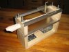
That's right. A length of tube will direct the air into the mouthpiece. A solenoid representing a recorder player's tongue will intermittently interupt the airflow to articulate notes.

Hank Fletcher said:
When playing the recorder, regulating the amount of airflow at any given time is important in fine tuning each note's pitch, so each note packet will also need at least an 8-bit representation of how hard the lungs should be blowing. The lungs on the first RCD-1 will be a modified camping mattress air pump, but I might use some custom bellows further down the line (air pumps can be noisy, even when run at low speeds).
 
There's going to be a whole load of mechanical noise coming from that thing not just flute noise =) I'd strongly recommend damping those solenoids with a good spring to avoid noise. No matter what you use for shielding you're not going to be able to damp the low frequency noise. If you use a heavily loaded solenoid (a stiff spring cut to cause it to try to return to a half way extended point would damp the thumps, if you could load the solenoid enough you could eliminate it altogther.
 
Last edited:
The second page of the 16F88 is the page not easily assessable (0x800 to 0xfff). You can store data using the DW directive and read it back with the EEPROM registers.

This is how I read it in a recent project,
Code:
ReadFlash	bsf	STATUS,RP0	;01
		bsf	STATUS,RP1	;11
		bcf	INTCON,GIE	; No Interrupts please
		BSF 	EECON1,EEPGD	; Point to PROGRAM memory
		BSF 	EECON1,RD	; EE Read
		NOP 			; Any instructions
					; here are ignored as
		NOP 			; program memory is
					; read in second cycle
					; after BSF EECON1,RD
		bsf	INTCON,GIE
		bcf	STATUS,RP0	;10
IncEEADR	incfsz	EEADR,f
		goto	DoneRead
		incf	EEADRH,f
DoneRead	bcf	STATUS,RP1	;00
		return

Before calling the above you setup EEADR & EEADRH to point to where you want to read. When it returns EEDATA and EEDATH (both in bank 2) contain the (14 bit) data. It also autoincrements the address.

The model railway solenoids are called "points motors". The reason I suggested boden cables is because of noise. Boden cables allow you to mount the solenoids/motors in a sound proofed box. **broken link removed**.

Mike.
Edit, there is no need to disable interrupts in the above code. I had to because I was writing to EEPROM in the ISR.
Also, here's a **broken link removed** to what I call boden cables. Refered to as pushrods.
 
Last edited:
Pommie said:
Before calling the above you setup EEADR & EEADRH to point to where you want to read. When it returns EEDATA and EEDATH (both in bank 2) contain the (14 bit) data. It also autoincrements the address.

The model railway solenoids are called "points motors". The reason I suggested boden cables is because of noise. Boden cables allow you to mount the solenoids/motors in a sound proofed box. point motor page.

Mike.
Edit, there is no need to disable interrupts in the above code. I had to because I was writing to EEPROM in the ISR.
Also, here's a link to what I call boden cables. Refered to as pushrods.
Thanks for the info and the links, Pommie. The boden cables will no doubt be of use to my plans for future robots playing larger recorders (they come in all sizes right down to contra-bass, which is about as tall as a small person!). Truth is, I've been scratching my head the last couple days trying to make sense of the code. I won't bother you to explain it to me now (although it certainly wouldn't fall on deaf ears... ...blind eyes?... if you did), because I still have to get my head around the very basics of a PIC. Fortunately, some 16F88s arrived in the mail today, so I'll get cracking with some remedial programming attempts this weekend.
 
Here are a few more photos documenting my progress with RCD-1 this week. The first photo is probably the closest picture I'll get to the first concept drawing. Wooden braces to secure the recorder have been mounted on the 1/4-20 stock, themselves secured with nuts and washers.

Some scrap pieces of acrylic sheet are posing in to give an idea as to how the final project will look - yes, the sheet's a bit mucky, but it also has a glare-resistant coating on one side, in case you're wondering. Also sitting in for final-impression reasons only are four 1/2" square aluminum rods. Although not presently attached, these rods will eventually be bolted to the acrylic sheet with some brass machine screws, and the acrylic sheet will in turn be sandwiched between the wooden braces with two holes on each end of each sheet to accommodate the 1/4-20 stock.

In the second photo you can see a small piece of acrylic sheet on top with a solenoid bolted onto the sheet, again just as a trial to help visualize the final thing. From this (fuzzy - sorry about that!) perspective it looks like the solenoid pin is quite far from the recorder, but it's only between 1/4" and 1/2" away. This gap will of course be taken up by the padding and retraction mechanism mounted to the solenoid pin.

The last two photos give an idea of how the recorder fits into the wooden braces, with a custom-cut groove to match the unique contours of the instrument. I should have some photos of something close to the final physical parts of RCD-1 by the end of the weekend, and I'll be sure to post them here. Then, it's on to playing with the electronics end of things!
 

Attachments

  • IMG_0360.JPG
    IMG_0360.JPG
    53.5 KB · Views: 259
  • IMG_0364.JPG
    IMG_0364.JPG
    38.8 KB · Views: 230
  • IMG_0369.JPG
    IMG_0369.JPG
    46.6 KB · Views: 241
  • IMG_0370.JPG
    IMG_0370.JPG
    50.5 KB · Views: 238
Last edited:
blueroomelectronics said:
Just thinking aloud.
Muscle wire? It's quiet.

But very slow?.

How this sort of thing has been done in the past usually used pneumatic actuators, fast and quiet - like anything else, it's been done many times before, over a number of decades.
 
Nigel Goodwin said:
...this sort of thing has... ...been done many times before, over a number of decades.
Depending on how general you want to be, attempts at automated musical instruments have been going on for, as far as I know at this point, about two centuries (automated trumpet player). If anyone has any documents, leads, personal accounts, etc. of that kind of thing, please let me know (PM or forum post as you see fit), no matter how trivial or incomplete your information may seem. Please use your discretion: instrument innovations such as the piano or pipe organ are not my main interest, but rather attempts to automate the practice of specific instruments, be they wind or otherwise. All are welcome, but the older the better.

Just thinking aloud.
Muscle wire? It's quiet.
My impression from what I could learn was that it was too slow, too expensive, and required too much more accommodation in mechanical design than something like solenoids, for example. As I've said before, there's obviously a coolness factor with something like muscle wire, but until it's more readily available, cheaper, faster, stronger, I'm going to opt for more traditional choices. Rest assured I'll be the first to hop on board as soon as it becomes practical to do so.
 
Last edited:
Hank Fletcher said:
Depending on how general you want to be, attempts at automated musical instruments have been going on for, as far as I know at this point, about two centuries (automated trumpet player).

Very true! :D

But I was thinking of micro-processor powered ones, which I've seen examples of using air powered actuators - not sure if I've ever seen a recorder or not?, but certainly something along those lines (not trumpets, or instruments with valves).
 
I have hundreds of these printer hammers from some old IBM printers. The coils are 5.4 ohms, and will work off 2 AA batteries, but a little weak. Work fine off 6 volts, but in the service book the control line says 60 volts. They are huge printers...

Anyway, I've got a dozen or so that have been inside the house. The rest are still on two of the printers, and one block of them in the carport. The outside stuff, I have no idea of the condition, been atleast 10 years of huricanes and severe storms, intense heat, but should be okay. If interested, PM me and I'll put some in the mail for you.

Of, work fine directly off a 555, adding a transitor driver didn't seem to have any effect. Haven't tried anything with a microcontroller. They aren't very strong, so kind of killed the millipede robot idea I had...

That's a AAA size battery for scale...
 

Attachments

  • PIC00005.jpg
    PIC00005.jpg
    85.5 KB · Views: 247
  • PIC00006.jpg
    PIC00006.jpg
    86.3 KB · Views: 233
  • PIC00007.jpg
    PIC00007.jpg
    86.4 KB · Views: 224
  • PIC00008.jpg
    PIC00008.jpg
    87 KB · Views: 229
Cool project.. I was thinking that for a final version, if you wanted to be able to store virtually unlimited tunes, I'd recommend considering an SD card. It's relatively simple to get an SD card interfaced to a PIC (maybe more difficult with the 16F88, I've done it with a 16F877 and 18F series mcus). You can get relatively quick speeds with the faster micros (I can get about 600kB/s with a 20mhz clock after all the overhead).

The most difficult part of using an SD card is the writing a driver for the FAT filesystem, but its considerably easier if you only need read only. Then you could stick your SD card in a computer and load it up with lots of music.
 
Stellarcore said:
I was thinking that for a final version, if you wanted to be able to store virtually unlimited tunes, I'd recommend considering an SD card.
Thanks for the recommendation. I think I saw carrier boards at Sparkfun or somewhere, I wonder if there's some SD card interfacing info I can find there, too, or elsewhere? I don't know anything about FAT, but I think it will be feasible to only have the PIC/robot read the SD card, and have tunes downloaded to the SD card from a CPU.
 
I'd thought I'd post a quick update on how things are going with RCD-1. Things are going well, although I've hit a couple snags. It's been a busy summer, but I still hope to have it playing by the end of August.

As I think I've mentioned before here, I've made a compromise on this prototype. Since the goal is only to be able to play at the level of a first-year recorder student, it will not be necessary for RCD-1 to half-hole any fingerings. This means only eight solenoids for a thumb and seven fingers, and another one at least for the tongue, although I haven't really thought that through on how to do that yet.

One bump was to find suitable rubber bands to return the solenoids after they've actuated. The rubber bands I'm using are from a popular office supply chain, and they're a bit strong. If the elastics are too short, the solenoids can't push with enough force to extend all the way. If the elastics are too slack, the solenoids that activate by pushing down won't return to their retracted position. My solution is to keep the rubber bands as long as possible, and pulling as close to the direction of motion as possible. To do this, however, will mean to have an extra beam of sorts lengthwise across the top of RCD-1. After being a bit bummed out that this will obscure the view, I've decided to push ahead and finish the plan with this modification nonetheless. In retrospect, the recommendation of Bowden cables was a good idea, and I fully plan on using those in the second prototype if not only to minimize the noise, but also to keep the mechanical aspect of the robot as least distracting as possible.

Programming RCD-1's brain, a 16F88 PIC mcu, has been a blast. I'm having a great time tinkering with the 16F88, and I think it will well suit the RCD-1. There's just enough memory on the PIC, I think, to accommodate the hardest tunes in a beginner recorder book I have. The hardest tunes are made up of about 100 notes of various pitches (all within an interval of a 9th) and rhythms (from sixteenth to whole notes). Breath control and fingerings are relatively easy to program, but I'm still struggling with the best way to calculate the timing of the notes. I'm trying to strike a balance between accommodating what the 16F88 can do, but while keeping the programming as close to what makes sense to musicians as possible, with the idea being to make it as easy as possible to re-program the 16F88 with different tunes.

Thanks for reading, and please share any thoughts! I'll get back at it and post some more on my progress in the next week.
 
Last edited:
Maybe you could use a H bridge (homemade or IC) to control the solenoids to return to the original position. THis would mean to get push/pull solenoids, which might not work. If you are using push solenoids, Rubberbands are your best bet. Get wide ones also, and you may not need to use a hole plugger.
 
How about a update? Did you figure out a good way to fix the solenoid return system? Hope it turns out well!
 
Status
Not open for further replies.

Latest threads

New Articles From Microcontroller Tips

Back
Top