Continue to Site

Welcome to our site!

Electro Tech is an online community (with over 170,000 members) who enjoy talking about and building electronic circuits, projects and gadgets. To participate you need to register. Registration is free. Click here to register now.

  • Welcome to our site! Electro Tech is an online community (with over 170,000 members) who enjoy talking about and building electronic circuits, projects and gadgets. To participate you need to register. Registration is free. Click here to register now.

Rcd-1

Status
Not open for further replies.

Hank Fletcher

New Member
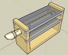
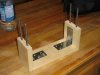
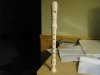
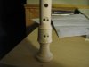
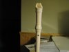
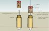
Here's a concept drawing of a recorder-playing robot I'm building. For now it's just the apparatus for holding the recorder. Solenoids will be attached to the acrylic sheet above and below the recorder to act as fingers. I'll post more pictures as I progress - I plan on having RCD-1 running by the end of August.
 

Attachments

  • RCD-1.jpg
    RCD-1.jpg
    31.6 KB · Views: 319
Here's what I was able to get through today. Some sturdy brackets are added (not shown in concept drawing) to support the vertical ends of the recorder holder. The wood is from a plank of pine. The four pieces of 1/4-20 bolt stock will be used to tighten down the other pieces seen in the concept drawing, but not yet seen here because I haven't made them yet!
 

Attachments

  • IMG_0347.JPG
    IMG_0347.JPG
    527.3 KB · Views: 288
Last edited:
Instead of solenoids how about something like common hobby servos's that could be used to move a sleeve on the flute up and down to allow variable amounts of the hole to be exposed? Ideally you'd want a modified hole shape to make the sleeve movement comlpetly linear but it would allow for significantly more control over the strength of the note's being played, allowing the ability to gives some 'feeling' to the music, or complex smooth note slides.
 
I don't know if I'm understanding you correctly, but the fingerings for the various notes on the recorder are not consecutive. Although generally lower notes use more fingers, that's only a very loose definition of what happens. In practice, covered/uncovered hole combinations can look to the untrained eye as almost random. Look up a fingering chart for the recorder and you'll see what I mean. Covering holes requires independent control of the first three fingers and thumb of the left hand, and all four fingers of the right hand. In addition, to play all chromatic notes over a two-octave range a technique called half-holing is required, which means the left thumb and right ring and little fingers must be able to cover both their entire hole and only part of their hole at any given moment.
 
Last edited:
...how about something like common hobby servos's that could be used to move a sleeve on the flute up and down to allow variable amounts of the hole to be exposed?
I get what you mean now. At first I had interpreted "amount" as "number." It's an interesting idea, but I think it's beyond the scope of this prototype. Truth is, I'm not too sure about the context for glissandi on the recorder, i.e. what it involves as far as finger placement on holes. Further to that, I can't really visualize what the mechanical means of accomplishing that might be in terms of having a way to cover the holes both quickly and at a slower, variable speed.
 
How are you going to interface it? My guess is that you could use a MIDI file and have it translated into serial/parallel signal outputted to a uC.

Becoming a bit like Animusic, non?
 
How are you going to interface it? My guess is that you could use a MIDI file and have it translated into serial/parallel signal outputted to a uC.
Actually, I started out this whole project by learning how to tear apart the contents of a MIDI file. The idea is to be able to write a composition in notation software like Sibelius, save it as a MIDI file, open the MIDI file in some translation software of my own design, and then send that to the robot. I don't know anything about interfacing an mcu to RAM (any tips/component suggestions out there on that?), so there are going to be some limits on what I can manage in the first prototypes. My idea for the first round is to actually just hard-program a PIC for a certain tune, thereby using the program memory to store the tune as oppose to copious amounts of RAM.

As an interim challenge I might try interfacing the robot with my computer's parallel port, although even then I'm not sure yet on what level, as in having the PIC interfaced to the port, or just manipulate the hardware, or what will be happening on the software end of things. In the end, I'd like the robot to have autonomous control, even if that just means playing a pre-programmed tune independently of a CPU after it's been switched on.

Becoming a bit like Animusic, non?
Although I don't know much about that field, I guess it is, and you're not the first one to have suggested it. From an etymological perspective, I suppose it's animusic, although I find that in itself to be a vague term.
 
How much memory do you need?

Could you use I2C EEPROMs instead of RAM?
Good questions.

There will be eleven solenoid "fingers" on the RCD-1. The reason for that is there will be one per hole for five of the fingers, and two per hole for the other six fingers in order to accommodate the latter three holes' need to be half-holed (I'll post a concept illustration in the near future for how the half-holing business will work on RCD-1). So getting to your first question, it will be possible to represent the fingering of a note to RCD-1 at any given moment with an 11-bit number. I'm guessing if I'm doing that on an 8-bit PIC I'll have to use two bytes (16 bits) to get all the fingerings in. I think I might use the leftover 5-bits for details like tonguing* (e.g. 1 = tongue, 0 = don't tongue) or an indication that the tune is over and to shut down the robot.

When playing the recorder, regulating the amount of airflow at any given time is important in fine tuning each note's pitch, so each note packet will also need at least an 8-bit representation of how hard the lungs should be blowing. The lungs on the first RCD-1 will be a modified camping mattress air pump, but I might use some custom bellows further down the line (air pumps can be noisy, even when run at low speeds).

Now here's the tricky part: rhythm. MIDI has an efficient method of dealing with rhythm by expressing durations as variable length quantities. But where the PIC's concerned (and if I'm using program memory to store this info), I think some concessions will have to made (in the music) to accommodate what the PIC can do (by itself - I'll get to the RAM-EEPROM thing in a minute). The plan is to use a 16F88 for the first prototype, and before the pundits chime in to suggest a better PIC (which I'm sure there probably is) bear in mind that I'm brand new to the world of mcus (hence my decision to go with a popular model). More than anything else involved in the project, the RCD-1 is an excuse for me to develop my own understanding of mcus. Anyway, back to rhythm. I still have three bits left from the fingering values I mentioned earlier, so what I might do is use those to call one of eight durations between a whole note and a sixteenth note long**, each duration being set as its own subroutine in assembly.

So that gets me to a minimum of 3 bytes per note to get the RCD-1 to play at something close to the same level of a first-year recorder student. You've probably caught on to where all this is heading: the entire length of any tune programmed into the PIC will be dictated by the programming space available, the minimum 3 bytes per note requirement, and how efficiently I can coordinate/process each 3 byte packet in the PIC. It should be enough space, like I said, for RCD-1 to play a tune at the level of a first-year student, but obviously further down the road I'd like to be able to expand what the RCD-1 can do.

Getting back to MIDI, in terms of playing the recorder the information in a MIDI file will quite likely be adequate to program a recorder robot to play at the equivalent of a very accomplished performer. That's because of two things: 1) the recorder, relative to other wind instruments, is more simplistic; 2) due to the nature of the recorder, the information for the technique it requires lends itself well to the way a MIDI file is designed. To compare, the same can't be said of a trombone robot, where the variables (i.e. to accommodate such techniques as a slide glissando or the increased options for articulation) are not readily manipulated in present music notation programs (although MIDI would be able to accommodate these things if composition software had a reason to exploit them, but that's another story). Back to the RCD-1: if future versions of the recorder robot are to be able to accommodate the information (or equivalent) in a MIDI file, based on a generous estimate of what I've seen in MIDI we're looking at about 10 bytes per note. Again, how much memory you have dictates how long a tune can be, but presuming that a long tune is 500 measures of four beats each at a rhythmic density of 1/32 notes, multiplied by 10 bytes per note, that's about 160KB. Admittedly, I'm being very generous here, but I think it's close to what to plan for.

Do you have any part suggestions for the EEPROMs? I've seen them here and there, but I still need to learn more about how they and I2C work. Any tutorial or supplier links would be appreciated!

*Tonguing means articulating the note on a wind instrument. So this bit will tell RCD-1 whether to play the note with a "Tu" sound, or whether to play the note without articulating (which is called slurring). The tongue on RCD-1 will probably be another solenoid that will close a valve that momentarily interupts the airflow to the recorder.

**In music, a whole note gets four pulses (or beats) and a sixteenth note get one quarter of a beat. For the robot, the tempo will be a constant for each program/tune, with the smallest pulse/increment being a sixteenth note.
 
Last edited:
Just an idea, I recalled MikeK8LH came up with an elegant servo controller that could easily handle 8 servos with little CPU overhead. A servo moving a tapered plunger could fill the hole in the flute partially or fully depending on the servo angle.
crazy-8-v4-png.12816
 
blueroomelectronics said:
A servo moving a tapered plunger could fill the hole in the flute partially or fully depending on the servo angle.
Thanks for the suggestion. With a 20ms period, wouldn't the servo in the schematic only refresh at about 50Hz? It's my impression that that would be too long of a time to delay, and cause noticeable performance issues particular if coordinating multiple recorder robots in the future. My plan for using solenoids for the fingers of RCD-1 will perhaps make more sense when I post my concept drawing for those sometime in the near future. I'm not too concerned about finesse, but more concerned about speed, for the first prototype. Perhaps if it was a tin-whistle robot the need for portamento playing and its inherent mechanics would be a bigger priority given the kind of repertoire common to that instrument, but for the recorder I don't sense that glissandi or portemento are that big deal from the repertoire I've seen. In the meantime, here are some photos of the Yamaha YRS-24B that will be used for RCD-1 to give you a better idea of what I'm up against. You'll notice that the holes for the third and fourth finger are actually double holes, and this is to make half-holing easier for human players, although I don't think it'll make much difference either way for RCD-1. The thumb hole is just a normal hole like most of the others, though, despite the need for it to be half-holed in order to play in the upper octave of the recorder. As I said, my simple plan for accomplishing that will make more sense once you see the concept drawings, so hang tight!
 

Attachments

  • IMG_0357.JPG
    IMG_0357.JPG
    33.3 KB · Views: 268
  • IMG_0358.JPG
    IMG_0358.JPG
    37.5 KB · Views: 257
  • IMG_0359.JPG
    IMG_0359.JPG
    32 KB · Views: 261
Last edited:
The 64K by 8 parts are fairly common. The ST M24512 or Microchip **broken link removed** are similar. You can use up to 8 of them on the same bus.

Both are 400kHz - Fast-mode part. They have a sequential access read mode. A data bit is sent back on each clock and the PIC must acknowledge each data byte. The ack is done in 1 bit time so you have 9 bit times per byte transferred. 400K/9 = 44.4K bytes per second, maybe a bit less.

A single master I2C tutorial

You can find the ST part here. Note the 12 day lead time.
Mouser has the Microchp part. I have used other serial buses but not I2C.
 
Last edited:
Why not just use a 16f88 and use the second page to store your data. That gives you 2K or read/write memory and each location can contain 14 bits. If you implement some kind of run length encoding you should be able to get a decent tune in there and latter you can implement a serial EEPROM and just load the data into the internal area.

Another thing you may want to consider is the small solenoids sold to control model railway points. These just need an impulse to flick them one way or the other. The bad news is that they require 12V for switching. The good news is they're very cheap and switch very fast. Model shops can also supply boden cables that allow the motor to be mounted remotely from where the movement is required.

Just some random musings.

Mike.
 
Pommie said:
Why not just use a 16f88 and use the second page to store your data. That gives you 2K or read/write memory and each location can contain 14 bits.
That was my original plan, and the one I'm going with to begin. What do you mean by the second page (sorry, I still have a lot of sorting through the datasheets on PICs)? Presuming I rearrange the 3 bytes per note I've mentioned above into two 14-bit words, then that'd give me 1000 notes for the prototype, which is ample. Is it naive of me to presume that I might be able to store data in a PICs program space this way though? I mean, what I'm proposing is essentially the same as using a DATA statement in BASIC - can this be done in assembly on a PIC?

Another thing you may want to consider is the small solenoids sold to control model railway points.
Hmm... my plan is to use some of these:
https://www.goldmine-elec-products.com/prodinfo.asp?number=G16333
but your idea intrigues me. I've tried googling for railway-hobby-solenoids but I haven't been able to find what you've described. Gotta link?
 
Here's the concept drawing of a solenoid modified for use with the RCD-1. The solenoid pictured is designed for only the recorder holes that are fully covered during playing, that is, the holes that don't need to be half-holed. I'll post another concept drawing of this solenoid in context as it will be assembled with the rest of the robot, and my design for the half-holing modified solenoid, shortly. For reference, the base part (thick part) of the solenoid is about 1" high and 1/2" in diameter. I make no claims for accuracy, as I'm only going by the info on the solenoid's website since I haven't received the actual thing in the mail yet.
 

Attachments

  • solenoid for RCD-1.jpg
    solenoid for RCD-1.jpg
    26.8 KB · Views: 281
Last edited:
I wonder how much noise the solenoids will make.
Same here. By far the hardest part about making automated musical instruments is the fact that most parts you can scavenge weren't designed with taking into account as a perogative how much sound they make during their normal operation. I don't suspect the solenoids will make much sound at all when activated, and as you can see from the concept drawing, their impact on the recorder will be cushioned by a sponge and piece of rubber. They're not moving very far, and they don't have to press very hard against the recorder. The thing I haven't fully taken into account is when they retract from the recorder with the elastic band - there'll have to be some sort of stop on the solenoid at the opposite end of the pin/finger to prevent the pin from jumping/falling out altogether, but again, whatever I use to stop the retraction can be spongy to limit the amount of operation noise.
 
Looking good! when can we expect the final product?

If you want to limit the sound coming from the solenoids, why not wrap them in foam or somthing? What about bubble wrap? I dont know what that would do, but its just an idea.
 
Looking good! when can we expect the final product?

If you want to limit the sound coming from the solenoids, why not wrap them in foam or somthing? What about bubble wrap? I dont know what that would do, but its just an idea.
As it says in the OP, the end of August, but I'm planning on sharing my progress on this forum for support and advice (so the suspense shouldn't kill you). The timeline is for an autonomous, single recorder playing somewhere close to a first-year student level, but the project will extend beyond the end of this summer to as far as I have the ambition, patience, and resources for. As far as sound insulation for the solenoids is concerned, I'm not going to get too carried away with ideas until I've actually got the things. Provided the pins are machined to fit the casings well, and enough cushioning for the extension and retraction, they shouldn't really need any insulation other than that. Remember, some of the sound from the robot (i.e. the recorder) I want to be able to hear, so that limits the options for sound insulation, and just from an esthetic point of view I'd like to actually be able to see as much of the recorder and the robot's mechanisms as possible (hence, for instance, the choice of acrylic sheet for mounting the solenoids).
 
I guess that is the best course of action. It would be better to get everything first and build it before you start thinking of upgrades. How are you going to feed air to it? Through a special pump connected to the mouthpeice?
 
Status
Not open for further replies.

New Articles From Microcontroller Tips

Back
Top