Electro Tech is an online community (with over 170,000 members) who enjoy talking about and building electronic circuits, projects and gadgets. To participate you need to register. Registration is free. Click here to register now.
Welcome to our site! Electro Tech is an online community (with over 170,000 members) who enjoy talking about and building electronic circuits, projects and gadgets. To participate you need to register. Registration is free. Click here to register now.
Yes.
Two things.
1
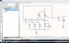
Each stage of phase-shift costs about a third of the power, maybe a little more.
The gain is insufficient, i recommend strapping another Tr across the existing one,
darlington fashion.
2
Also that four and a half megohms is too high. (As has been mentioned.)
Biassing.
Disconnect that train of caps, adjust till you get between 3 and 6 volts on the collector
of the output, then reconnect the train of caps.
Good point. Although it usually isn't shown on schematics, it might be a good idea, for your circuit, to capacitively couple the feedback network to your base. Alternatively, some oscillators connect the 3rd stage resistor to the base, rather than ground.
R2 should be connected to the collector. The 560R's should be about 22k. R1 should be about 4k7. If you follow the convention of putting the "k" between the figures, we won't have the problem of trying to work out what values you have used.
Thanks for all those tips , i will try to test each and every one of those .
By "dead" i meant i made a prototype and i dont see anything on the oscilloscope !!!
i will give you feedback after adjusting some the R's and C's.
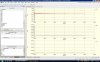
here is the new schematic and its results simulated in altium .
The missimg junction really helped , i wasnt able to simulate it first .
I wont alter the prototype as yet , once i get it running in simulation.
As the simulation shows oscillations die down after some time ???
Ok , but the supply is 12v , how do i translate the same %age of gain using 9V DC ??
i am a bit rusty on analogue design .
How to calculate the values of emitter bias and base bias Resistors??
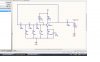
the built ckt works , i have made the ckt as posted by MikeMI .
the output frequency is 546.5hz .
to make this ckt for higher frequencies i am using the formula : f=1/2*pi(2N*RC)^0.5.
is this rite ??
This site uses cookies to help personalise content, tailor your experience and to keep you logged in if you register.
By continuing to use this site, you are consenting to our use of cookies.

")