timjohnson
New Member
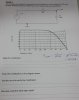
Hello, I'm a beginner in electronics, sorry if what I'm asking is basic. I have a task for one of my assignments which I'm unsure about. It is about RC LPF filters. I am asked to modify a circuit so the cut-off frequency is doubled. How would I go about doing so? Would I simply reduce the resistor or capacitor value for the formula: F(cutoff)= 1/2piRC. Also how would I show this practically? My lecturer says to keep the amplitude of the input constant but I'm not sure what he means by that. The circuit consists of just a signal generator, supplying a resistor of 1k and capacitor of 100n and a Vout measurement between the resistor and capacitor. Any help would be great. I have also attached an image.