Follow along with the video below to see how to install our site as a web app on your home screen.
Note: This feature may not be available in some browsers.
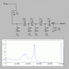
Well... R4, C1 through C6 and L1 and L4 are the only part that will affect Node6 as V1 changes assuming there is very little resistance within the V1 source.
R4 and C4 are basically a low pass RC filter .... The remaining circuit is a low pass PI filter hybrid ... composed of a "T" filter between L1,L4 and C1, while also composed of a "PI" filter between C3,L1,L4, and C5. Other fundamentals could be found at C3,L1 and C1 as well as C5, L4, and C1. C2 and C6 provide some buffering and DC bias.
Reference:
https://www.radio-electronics.com/i...f-filters/simple-lc-lowpass-filter-design.php
Are R1, R2, and R3 just hanging in the air so as to pick up spurious signals? Or, are they connected to ground? Where is the output, node 6? If so, document and label it. Does the filter have any load? If so, what is it?hi guys,
Is it possible for anybody to shed some light on the manual calculation (how to proceed on calculating the filters) based on the components used?
I have attached the components used.
Thank you for the help!!
View attachment 114789
Are R1, R2, and R3 just hanging in the air so as to pick up spurious signals? Or, are they connected to ground? Where is the output, node 6? If so, document and label it. Does the filter have any load? If so, what is it?
Looks like you can write out 6 node equations and put them through an equation solver. Then graph the node response you are interested in. Need help with that?
Ratch
can i get some help on that?
additionally, issit possible for me to just and calculate an overall value based on the capacitor and inductors used and calculate their cutoff freq using
1/2pi(sqrt L and C).
Thank you so much for your help. The R1, R2,R3 are connected to different parts of the schematic so i assumed since they play no effect in affecting the signal coming through to node6, i can just ignore them since it will be troublesome and heavy on the circuit to input all of them together. BUt, if you want, i can put them all through one circuit and put it here.
Thanks again!
Hi! Thanks for your help!NO, you must use calculate the currents coming/going from/to each node. That means doing a node analysis. You can combine parallel capacitors between each node, however. Use a computer to do the grit work.
If those resistors are connected to some low impedance point, then they probably will affect the filter output. You can determine the difference by running the calculations with the resistors first grounded and then open.
Ratch
Ahh sorry the schematic at the start is just now at a different node as compared to the overall circuit.Now you got me confused. In first schematic, you show R4 going to a capacitor. In the second schematic R4 goes to a coil. I think it is best if you use the Spice program to determine the voltages and currents. The circuit is too complicated for manual calculation unless you can first determine where you can separate the various parts of the circuit where they do not interact with other.
Ratch
from what i know, it is to only allow a specific frequency to pass through and nothing else.
I know of no such limit.LTSpice is node (and device) limited.
no no thank you i needed that to further press on and ask more on the application of the circuitry.OK, being quite brutal about this, but, knowing nothing is not a good start for circuit analysis.
As for "allowing a specific frequency to pass through", nonsense!
It is a whole load of low pass filtering and a DC block (C2 and C6).
Where did you get this circuit?
It did not just appear out of thin air, surely?
As I said earlier, it is bizarre, surely not a practical circuit by any stretch of the imagination.
JimB

