Hello there,
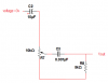
Here is a formula for the output of your original circuit, assuming the 10uf cap is passing the frequencies of interest with little loss (a very reasonable assumption) and the input is a sine wave:
Vo=Vin*R7b*w*C3*R8/sqrt(w^2*C3^2*(R7b*R8+R7a*R8+R7a*R7b)^2+(R7b+R7a)^2)
where
Vin is the input voltage
w=2*pi*F
R7a=upper pot resistance
R7b=lower pot resistance, also equal to 10k-R7a when R7 is 10k
C3 and R8 as per your schematic.
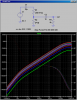
Note that the above formula is dependent on both the input voltage Vin and the frequency F, and also the pot setting.
You can substitute R7b with 10000-R7a so you only have to set R7a (the upper part of the pot).
Example 1:
What is the output amplitude when the upper part of the pot is set to 4k and the input voltage is 3vpeak and the frequency is 100kHz?
First, R7a=4k and R7b=10k-4k=6k, F=100000, and Vin=3 (peak) so the output is:
Vo=1.189v peak
Example 2:
What is the output with the same pot setting and same input voltage, but with F=10kHz instead?
The only thing different here is the frequency F=10000, so the output is:
Vo=0.5128 volts peak.
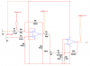
If you do not want to assume that the 10uf cap passes all frequencies of interest, then you'll have to use the more complicated formula which also includes C2:
Code:
Vo=(Vin*w^2*R7b*C2*C3*R8)/(sqrt((-w^2*R7b*C2*C3*R8-w^2*R7a*C2*C3*R8-w^2*R7a*R7b*C2*C3+1)^2+(w*C3*R8+w*R7b*C3+w*R7b*C2+w*R7a*C2)^2))
Note that the small cap 0.001uf dominates so the simpler formula is good down to around 10Hz or a little lower. Lower than that the amplitude gets pretty small anyway though.

")