Electro Tech is an online community (with over 170,000 members) who enjoy talking about and building electronic circuits, projects and gadgets. To participate you need to register. Registration is free. Click here to register now.
Welcome to our site! Electro Tech is an online community (with over 170,000 members) who enjoy talking about and building electronic circuits, projects and gadgets. To participate you need to register. Registration is free. Click here to register now.
The output of U11 is centered about GND, but the output of U13 is just DC at the opamp's maximum positive saturated output value. Are you asking about adding a DC component to the output of U11 before it goes to U13? This can be done with a coupling capacitor and some bias resistors.
The output of U11 is centered about GND, but the output of U13 is just DC at the opamp's maximum positive saturated output value. Are you asking about adding a DC component to the output of U11 before it goes to U13? This can be done with a coupling capacitor and some bias resistors.
If you made the (+) supply +10V, the negative supply = 0V, and what was gnd now is +5V.
Now your output will be from +1V to +9V.
This is close to what you want.
If you made the (+) supply +10V, the negative supply = 0V, and what was gnd now is +5V.
Now your output will be from +1V to +9V.
This is close to what you want. View attachment 105527
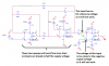
The voltage circled in red sets the center of the wave form. Try setting this to 5.5V or 6V and watch.
R11 & R12 set the end points. I am doing this in my head so might be wrong. lol
Don't go much bigger. It will stop working close to 100k, and above.
R13 & C3 sets the slope. Volts/uS.
The voltage on the power supply pins (+5, -5 OR +10, 0V) should cover the output you want. (probably should be one or two volts larger in range than the output.
i have triangle signal ~-4 - +4, but i need 0-5V, that's why i asked about elements of circuit, because if i change voltage i loose PWM signal after comparator
The capacitor you added prevented a reference voltage on the (+) input of the 3rd opamp.
Your SIM program did not read the datasheet for the TL031 opamp:
1) The TLo31 opamp inputs do not work if they are within 1.5V from the -5V supply but your 3rd opamp has its (- ) input directly at -5V so it will not work.
2) The output of a TL031 opamp cannot go anywhere near the +5V power supply voltage, some will go only as high as +3V.
The stupid SIM might work but the real circuit will not work.
1) An opamp cannot work without a DC reference voltage on its (+) input within its common mode input voltage range.
2) The output of a TL031 and most other opamps cannot go anywhere near its +5V supply voltage.
The stupid SIM might work but the real circuit will not work.
1) An opamp cannot work without a DC reference voltage on its (+) input within its common mode input voltage range.
2) The output of a TL031 and most other opamps cannot go anywhere near its +5V supply voltage.
Maybe the huge value of your capacitor C4 takes a few days to charge with the very low leakage current of the Fet-input opamp.
Here are the other problems with the opamp U13:
Maybe the huge value of your capacitor C4 takes a few days to charge with the very low leakage current of the Fet-input opamp.
Here are the other problems with the opamp U13:
This site uses cookies to help personalise content, tailor your experience and to keep you logged in if you register.
By continuing to use this site, you are consenting to our use of cookies.