Continue to Site

Welcome to our site!

Electro Tech is an online community (with over 170,000 members) who enjoy talking about and building electronic circuits, projects and gadgets. To participate you need to register. Registration is free. Click here to register now.

  • Welcome to our site! Electro Tech is an online community (with over 170,000 members) who enjoy talking about and building electronic circuits, projects and gadgets. To participate you need to register. Registration is free. Click here to register now.

Radio transmitter wavelength

Status
Not open for further replies.
Hello again. I just was just wondering in a radio transmitter what exactly is it that determines the wavelength of the radio wave being emitted? Thanks in advance!
 
The facetious answer is "The same things that determine the frequency"

JimB
 
The wavelenght L is the propagation speed of the radio wave s divided by the frequency of the wave f.

L = s / f

Usually the speed of light 300,000,000m/s is taken as propagation speed.
Example : the wavelenght of 150 MHz is: 300,000,000 / 150,000,000 = 2 metres.
 
From another angle, the frequency (and therefore wavelength) are set by the oscillator frequency (and any multipliers or mixers etc.) that produce the transmitter carrier wave frequency.

For the little DIY one or two transistor FM transmitters, the oscillator runs on the transmit frequency.

For serious communications radios, the oscillator frequency may be set by a quartz crystal then that fed through doubler or tripler stages to get to the required transmit frequency.

Or the modulated signal may be produced at a fixed frequency such as 21.4MHz (to make it easier to filter) then that mixed with a a separately generated signal from a crystal or synthesised oscillator, offset by 21.4MHz from the final frequency.

Some radios use several different intermediate frequencies and mixing stages to achieve the final output frequency.

Examples -
This is a block diagram for a relatively simple crystal-controlled radio; the lower half is the transmitter.
p13.gif
It shows the approximate frequency at each stage; from a crystal around 12MHz, which is tripled then doubled twice for an output frequency around 144 - 146 MHz; 12x multiplication.
(eg. for 145.5 MHz, the crystal would be 12.125 MHz)


Page 21 in this file shows a block diagram of a single-band handheld FM radio.
It also shows how a typical frequency synthesiser works, on page 14.

See page 3 in this one for a block diagram of a fairly complex multi-band radio:
 
in a radio transmitter what exactly is it that determines the wavelength of the radio wave being emitted?
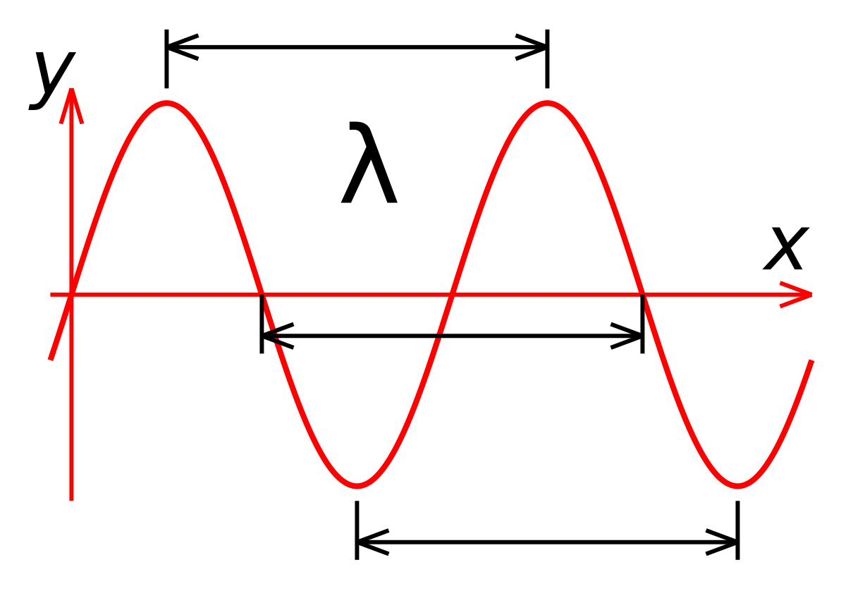
The frequency of oscillation and the velocity of propagation in the medium. You could have looked up this anywhere:


For a radio transmitter, the velocity is the speed of light in air, which is slightly different from the speed of light in a vacuum, and significantly different from the speed of light in a coax cable.

ak
 
Last edited:
You could have looked up this anywhere:
but of course the first three hits usually say something like "find the best prices for radio wavelength.... free shipping...."
 
The speed at which radio waves travel through space is equal to that at which electrical energy travels through a bare conductor (ignoring the conductor's velocity factor*) and that is the speed of light 'c'.

The distance travelled by either of them in one cycle is known as the wavelength 'λ'.

Wavelength 'λ' = Speed of light 'c' / frequency 'f'.

- Nandu.

* Velocity factor for a medium is the ratio of velocity of propagation in that medium to the velocity of propagation in free space. Velocity factor for bare copper wire is 0.95. It is lower for insulated wires and is as low as 0.66 for coaxial cable.
 
Last edited:
The speed at which radio waves travel through space is equal to that at which electrical energy travels through a conductor and that is the speed of light 'c'.
that is a bit inaccurate... "c" in a vacuum is different from "c" in coaxial cables for instance (and without the speed of light being different in solids or liquids to cause refraction we wouldn't see clearly). "c" in a straight piece of wire is 0.95 of "c" in a vacuum, this is why antenna lengths are calculated with a correction factor. for other conductors,(again using coaxial cable as an example) both the construction and insulating materials have an effect on velocity, with some types of cable having velocity factors as low as 0.66. this is why, when making 1/4 wave stubs, someone not knowing this will calculate the wavelength the stub is to resonate at, and find it's way too long when they actually cut it.
 
and find it's way too long when they actually cut it.

Luckily they can always cut it shorter once they realize the problem. If physics worked the other way, they'd be in trouble. Or, maybe if physics worked the other way, they'd be able to cut the stubs longer if they started out too short. :D
 
another example of radio waves not always travelling through various things at a uniform velocity is ionospheric refraction and tropospheric ducting.
 
Luckily they can always cut it shorter once they realize the problem. If physics worked the other way, they'd be in trouble. Or, maybe if physics worked the other way, they'd be able to cut the stubs longer if they started out too short. :D
it's hard to always know the velocity factor of various things... fortunately we have various tools such as antenna analyzers to help with the work... of course with a decent pulse generator and an oscope one can measure the velocity factor of various cables simply by "pinging" a known length of cable and measuring the time delay of the reflection. since it it known the pulse has traveled twice the length of the cable, you can then calculate how many meters per nanosecond the pulse traveled an divide by c, which will give you the velocity factor. for obvious reasons, the longer the cable sample, the more accurate you can make the measurement.
 
Status
Not open for further replies.

Latest threads

New Articles From Microcontroller Tips

Back
Top