Continue to Site

Welcome to our site!

Electro Tech is an online community (with over 170,000 members) who enjoy talking about and building electronic circuits, projects and gadgets. To participate you need to register. Registration is free. Click here to register now.

  • Welcome to our site! Electro Tech is an online community (with over 170,000 members) who enjoy talking about and building electronic circuits, projects and gadgets. To participate you need to register. Registration is free. Click here to register now.

Radio control by location

Status
Not open for further replies.
From the d/s:
When Timer1 is enabled, the RC1/T1OSI and RC0/
T1OSO/T13CKI pins become inputs. This means the
values of TRISC<1:0> are ignored and the pins are
read as ‘0’.
Hi J,
Well spotted.
I think we've been here before, but if I'm correct, that was before I added a separate PIC for SERVO control.
I'm now looking at TMR2 instead, and probably have some programs to look at, with TMR2 in.
Thanks.
C.
 
Hi,
I always get mixed up between TIMERS and INTERRUPTS.
I've just realised that I don't need a TIMER, only and INTERRUPT. Now the TIMER has gone, the PIC is now talking to the 5100 SCREEN.
There is a still a problem, as nothing is showing on the SCREEN, and I think it's because of either timing or wrong direction SCREEN SWITCHES (CS etc)
C.
 
Hi,
Here is the latest program:
Now there are no INTERRUPTS or TIMERs
All of the modules apart from the LCD5110 are working.
I've had ussues in the past with the screen, as they are prone to problems.
C
 

Attachments

  • 18F4620 8MHz XTL RX 5110 GPS BMP280 AK8963C HC-12 090119 1100 TEST.bas
    23.6 KB · Views: 238
Are RCO, RC1 working now?
Hi J,
Yes, both working.Would it be of interest for me to post a logic analysis of the SCREEN PINS while running?
EDIT: Thanks for spotting T1con.
C.
 
Last edited:
Hi,
I think I've found the problem!
5110 LCD C/S is not working all of the time, although it is switching sometimes.
It's difficult;t to see in simulation, as it disappears.
C.
 
Maybe the lcd is set on in the included fontsml. bas?
Can you show the file.
Hi J,
EDIT: File removed, as it was irrelevant [I found this in an earlier working program, which may be a clue:}
Here is the Font file.
C
 

Attachments

  • fontsml.bas
    3.9 KB · Views: 251
Last edited:
This should work
In wr_msg(....)
move lcd_cs=1 - > just before End Proc
Hi J,
I tried the above, and nothing!, but the 'logic analysis' looked good, so I pressed the screen and got feint digits. (I mentioned this in #63)

Changed the screen and WORKING!

We've reached a milestone! All of the modules are working for the first time. The Compass shows direction, but needs refining a bit, everything else looks good.

The 5110 shows it's 20.03C and 103423.20 air pressure here.

We've been working on the REMOTE PCB, which now needs programming to control MOTORS/SERVOS.

The BASE PCB is very similar, and fits into a RC Transmitter, which needs programming so that the KNOBS/POTs will control the TX.

Thanks very much 'J' and all others that helped.

C.
 
Hi,
I'm switching to the BASE PCB now. This will be fitted into an Rc Transmitter, using the controls to send DATA to the REMOTE.

I've decided that if possible, I will add a Rotary Quadrature Encoder Interface (QEI), as one channel called COMPASS.
Here is a program written by Eric Gibbs, for my TRACKER. The program, uses the 18LF2431 QEI for counting the impulses from the QEI. The resulting number will be sent to the REMOTE as a COMPASS bearing for the REMOTE to turn to.

First, is this a suitable program to start with?
C.
 

Attachments

  • Test2431_V2.bas
    4.3 KB · Views: 234
Last edited:
Hi,
The Altitude, Compass and GPS are all now being READ and showing on the 5110 Screen.
Note the TEMP word is spoilt by the LAT READing overflowing, needs curtailing.

Next to fit this TX PCB into the Transmitter, and connect the Incremental encoder and the Stick POTs.
C.
 

Attachments

  • 5110.jpg
    5110.jpg
    171.3 KB · Views: 260
Hi,
I've now connected the STICK pots, and INCREMENTAL ENCODER and they are working.

This is a milestone, as all of the Transmitter modules are working, and it's only taken a couple of years :)
C.
 
Hi,
For a couple of months now, I've been getting an intermittent error from the AK8963C Compass module. (It either starts or it doesn't start) Testing with an analyser shows DATA arriving at the PIC MISO PIN. There are 5x COMPASS modules and 3x different PCBS, al showing similar error results.

My question is: The AK8963C was working for months, but now errors, what area would be the most likely to need investigation to find this fault.
C.
 
Last edited:
Hi,
An update:
I've been mainly using the AAC forum for advice, and can report that I 'WE' have all of the peripherals working.
Plenty more tuning up to do, before programming both PCBs to control the REMOTE.
Here is the latest Terminal view:

C
 

Attachments

  • All working.jpg
    All working.jpg
    94.7 KB · Views: 248
Hi,
At last the transmitter and Receiver are talking to each other. I few corrections to find, but generally good.

The next thing I've got to do, is convert the Transmitter Joysick, Encoder, location etc DATA into Motor control on the Receiving PCB.
Does anyone have any experience of this please?
C.
 
Hi,
I've been working on another thread, writing (With help) a 'self test' calibration plus 'average' program. Now that's done.
I also work on AAC, as if I get stuck for a while, I switch, in hope of an answer.

I now have 3x programs, the above, a transmitter (BASE) and a mobile (REMOTE). All appear to be working.
Next is quite different! I/we will start adding the CONTROL to the programs.

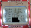
ALT uses the Barometers.
On the ground, at initialisation, both will READ the same.
Moving the Throttle stick FORWARD will tell the REMOTE to go HIGHER than it is, and Visa versa.

DIRECTION of AIM.
I'm not sure yet, whether this will be calculated, or use the BASE DIR knob.

LAT LONG. I think at first, the field of view should be as a matrix as LAT LON on a map.
Move the LAT stick to the RIGHT and the REMOTE moves RIGHT, and visa versa, similar for LON.

There should be a readout, say ALT MTRs. LAT LON MTRS and DIRECTION, which if calculated will need to be sent back.

The REMOTE only needs to send back battery voltage and necessary telemetry, as we know where it should be, even if it loses signal.
C.
 
Status
Not open for further replies.

Latest threads

New Articles From Microcontroller Tips

Back
Top