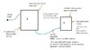
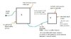
The attached is our setup going for radiated emissions testing. (It’s a kiddies play panel for hospitals and doctors gaming.)
What do you think to the following edicts on the radiated emissions testing ?.....(30MHz to 1GHz)
A…..Adding an RC snubber from switching node to ground at the Buck SMPS may well have a good effect. However, the sudden discharge of the snubber capacitor simply means there will be another radiated emissions problem, but above 1GHz, where formal testing does not take place?
B…….If we use common mode chokes with Y capacitors to the chassis, then any failure peaks that we may get are just as likely to be coming from resonance in the common mode LC filter, as from genuine noise emissions? As such, tweaking the Y capacitor value to try and bring peaks down is likely to be futile, as it will just mean getting a resonant peak at a different frequency? (So if we get failure peaks, how do we know if its noise, or just filter resonance, needing a damping resistor across the common mode choke inductors)
C……The cable connecting units A and B could be made of 2 core cable (not twisted) with a metal foil screen…or twisted pair with a foil screen. Can you confirm that 2 parallel conductors covered in metal foil screen would radiate more than twisted pair inside a screen?
D…….If I do a radiated emissions test in a proper radiated EMC chamber…but of a battery supplying a Buck converter in a metal chassis via a cable (ie, a cable from the battery to the chassis containing the buck)…then will the emissions be worse if the chassis is connected to earth ground?……or will emissions be worse if the chassis is not connected to earth ground at all?
E……The buck converter in the attached supplys some radio pagers via a wire loom. (5V, 0.5A to each pager). Suppose we put a common mode choke at the output of the buck, just before the connector that connects to the loom…..is there any circumstance where adding such a common mode choke could make radiated emissions worse?
F….For the blue cable in the attached…..which is best for low emissions?...
a)….2 core cable (unscreened)
b)….twisted pair (unscreened)
c)….3 core cable with 3rd connector connected between the two chassis’s (unscreened)
d)… 3 core cable with 3rd connector connected between the two chassis’s (screened)
G.......Why on the entire web are their No forums, or sub-forums, for people to ask questions about EMC testing of products?....is it because the actions taken to get kit through EMC testing is the deepest secret of any company?
H....For good EMC performance, why is it said that a capacitor with high SRF is needed to be connected right at the input/output connectors? (diff mode)