Continue to Site

Welcome to our site!

Electro Tech is an online community (with over 170,000 members) who enjoy talking about and building electronic circuits, projects and gadgets. To participate you need to register. Registration is free. Click here to register now.

  • Welcome to our site! Electro Tech is an online community (with over 170,000 members) who enjoy talking about and building electronic circuits, projects and gadgets. To participate you need to register. Registration is free. Click here to register now.

Quiz Project

Status
Not open for further replies.

Ferguson

New Member
I wish to put together an electronic controller which when asked a question the contestant pushes a button thus activating a light and buzzer, but also eliminating the other contestants. This then is reset for the next question.

I am a total novice and also this probably has been answered previously but there is a lot of threads to review. I did down load a project from RSH electronics and reviewing their diagram. Any easier projects will be appreciated.

Thank youΩ
 
The simplest way to do this would be with a microcontroller but if you are an extreme novice it could take you a while to get up to speed. Don't get me wrong, I encourage you to learn and if you want to go that route there are people here who can help you. However, if you would like to pursue a solution other than the microcontroller, what you want to do can be accomplished by using standard logic ICs. I threw together a circuit that will probably work for you and you can scale it up or down for as many contestants as you'd like. Someone please double check this for me.
 

Attachments

  • Trivia_circuit.JPG
    Trivia_circuit.JPG
    174.7 KB · Views: 2,154
Last edited:
Thank you I will look at it and compare with what I have downloaded as noted and I AM a novice but willing to try anything. Did put together a computer (assembled parts).
 
quiz circuit

I have attached a schematic of what I was working off of. I may need to take these to someone in the know.
 

Attachments

  • Quiz circuit (1).pdf
    466.1 KB · Views: 649
the schematic that VNE147 posted????

won't prevent the other contestants from sounding the buzzer. At least after lookng at it several times??
I built such a circuit years ago, two teams with lights n front of each player.
a buzzer and when ANY player pushes their button it prevents ANY other button from working.
don't have any schematic but recall it used several D flp flops, couple of multi input nand gates.
will try and develope this schematic.
basically it was several D flip flops (one each player)
if any flip flop was clocked (button push) it prevented a HGH input on all the other flip flops.
The circuit that vne147 shows does not cancle out any oher input.
 
the schematic that VNE147 posted????

won't prevent the other contestants from sounding the buzzer. At least after lookng at it several times??

I don't think this is true. The outputs of the 4013 D flip-flops are dioded, tied together, and then inverted before being fed into AND gates that are between the pushbuttons and the 4013s. If the output from any one of the 3 4013s goes high, it is inverted into a logic low which makes the output of the three AND gates to the left of the schematic go low. The output of these AND gates will remain low regardless of additional button pushes because one of the required 2 inputs will remain low as long as the output from any one 4013 remains high. That is how I intended it to work anyway. If I'm missing something please let me know.

I'm sure this circuit can be improved upon. It's just something I threw together quickly after a minimum of thought. The OP doesn't have to follow it verbatim, I just wanted to give him some ideas. One issue I have realized since I posted the schematic is that the buzzers will continue to sound until the reset button is pushed. You may want to tie the output of the 4013s to a 555 stage so that the buzzer only sounds for a second or two but the light stays on until the reset button is pushed.
 
Last edited:
Sorry, I double replied by accident. Admins can delete this reply if anyone cares. Thanks.
 
Last edited:
here is BASIC idea

I recall when I built similar circuit.
Basic idea is when a button is pressed it clocks its separate D flip flop.
upon clocking on rising edge the /Q output disables all the other push button inputs via NAND gate (HIGH(button), HIGH(/Q output) = LOW clock for all other push-buttons(clk inputs) which prevents all other D flip flops from clocking.
I may not have the schematic right but general idea.
 

Attachments

  • quiz.PNG
    quiz.PNG
    26.5 KB · Views: 1,068
Game Circuits About as simple as it gets. I've used it and a lot of variations, and it works well. Just add a Sonalert or other piezo buzzer across the top-left lamp. :)

Ken
 
I do wish to thank you for your responses. I see some terminology I do not know like flip flops etc. I guess i need more homework and like I said I am real novice. But will give it a try. Live in Austin, Tx. I will try to wear out the patience of Frye's electronics personnell or another store. Does Radio Shack have the parts and personnel for this type of project?
Again I thank you. I am the type if I see it I can usually do it but...we'll see.

In my experience Radio Shack is mostly useless. They have some parts but even fewer people that are able to give useful advice. Fry's has a much better selection of parts but will likely still be lacking in the advice depertment.

Some homework will definetely be useful. A flip flop is just the name given to a bi-stable circuit that changes it's ouput based on an input. In other words, the output flip flops from hi to low or low to hi to match an input. Read this:

https://en.wikipedia.org/wiki/Flip-flop_(electronics)

Before you build this circuit you'll want to test it out on a solderless breadboard like the ones shown here:

Breadboard - Wikipedia, the free encyclopedia

It will allow you to verify that the circuit works prior to soldering everything together and also help you to understand everything that's going on which will aid you when building the final product. You can buy a solderless breadboard and jumper wires at Fry's.

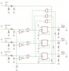
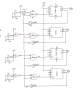
I did test out the schematic that I posted in a circuit simulator and it seems to work. There are a few things that I've realized I can simplify since I originally posted it. If you decide to go with my idea, I can send you an updated schematic.

Also, once you decide what you're going to build, I would recommend ordering your parts from Mouser. They are here:

Mouser Electronics - Electronic Component Distributor

I live in Houston and I order almost all my parts from them. They are located in Dallas, so even though I always only pay for normal UPS ground, it almost always arrives the next day.

If you want, once you decide how you're going to procede, I can assemble a parts list and send it to you can just go online an get everything from mouser.

Good luck.
 
Last edited:
Mouser is number one on my list for parts.
Goldmine is another favorite for really good prices but you need to know what you want.SALE! Giant CDS Cell Assortment-The Electronic Goldmine
SUGGESTION= build using a solderless breadboard. If a real novice I suggest staying away from anything that have large current potiential (stick with battery circuits only)
build in sections, get each section workingthen add to it.
example - construct a simple D-flip flop circuit (4013 or 74ls74) first using leds for indication of states..
If using CMOS (IC parts with a C in part number) are prone to static electricity. If just getting into this then go with TTL, LS type IC's. BATTERY POWERED at 5 volts max(3 AA batteries for testing)
 
i need help with a project i have to create a quiz referee circuit with a d-type flip flop. i it will have a 2 switch for each contestants and a corresponding LED. it will also have a reset. however i do not know how to create or join them. and i do not really unnderstajnd electronic much. plz help.
 
i need help with a project i have to create a quiz referee circuit with a d-type flip flop. i it will have a 2 switch for each contestants and a corresponding LED. it will also have a reset. however i do not know how to create or join them. and i do not really understand electronic much. also i need to know how will it work. plz help. ps a diagram would be benificial. thanx.
 
Need more info
Why two switches per player?
I think if you type in quiz game circuits you WILL find what your looking for
 
sorry, only one for each player. i need to know how to create a circuit only using a d-type flip flop one for each player, a push button and couple of resistor, and it must have a reset switch. also i need to find out how to disable the opponents switch so they wont able to start it when the other player hit their switch first. and some explanation would help cuss I'm not really good at electronics.
 
Is this a class assignment?

Ken
 
I have a hunch it is a class assignment.
About this time of year we get lots of posts that turn out to be homework/class assignments
I suggested to do a search -- zilch
I post a link -- probably the last we hear of this project as now the op has a circuit in hand.
sorry if I sound harsh but seen TOOOOO many of these.
 
Status
Not open for further replies.

Latest threads

New Articles From Microcontroller Tips

Back
Top