Continue to Site

Welcome to our site!

Electro Tech is an online community (with over 170,000 members) who enjoy talking about and building electronic circuits, projects and gadgets. To participate you need to register. Registration is free. Click here to register now.

  • Welcome to our site! Electro Tech is an online community (with over 170,000 members) who enjoy talking about and building electronic circuits, projects and gadgets. To participate you need to register. Registration is free. Click here to register now.

Quiz competition game circuit

Status
Not open for further replies.
This is my circuit so far...I have the problem of attachig the adder to the jeopardy circuit,,and also how can i store the points of players
 

Attachments

  • untitled.JPG
    untitled.JPG
    37.1 KB · Views: 338
Save the file as a .jpg, a gif, or a .png. ( I like .gif...B&W only, others prefer .png)
When you post, select the "Go Advanced" button at the bottom.
Go down to "Attachments" and select the "Manage Attachments"
In the top panel select the top "Browse" button.
Find your saved file on your computer a,d ricgt click on it.
Select the "Save" button. This will put you back in the "Manage Attachments" panel.
Select the upper "Upload" button.
Your file name should appear above the "Attachment Key" panel
If it isn't there, look at the top of the Window. Likely the file is too big. See the "Attachment Key" panel for acceptable sizes.
Select the "X" (close) button in the upper right corner.
Your file image should appear at the bottom of the post editing panel.

Ken
 
Does it work the way you want or not? Are you using TTL or CMOS chips?

Ken
 
No...I am not using TTL or CMOS chips because we havent been taught those yet,and so far the circuit is not working,,I dont know what the problem is...
 
I can get the jeopardy circuit working,there must be some connection errors,BUT the main problem is that HOW can i attach binary adders at the end of it to add the scores of the playes,,What would be the connection logic
 
Have you just learned logic gates, but not built anything yet? Are you using logic simulators to test your circuit? Or, are you just implement truth tables on paper?
Ken
 
My concept was to have an up-down counter with a BCD output.
The BCD output feeds a BCD to 7-segment display converter.
Each counter has an "up", "down", and "enable" inputs.
When a contestant locks-in, the output of their Jeopardy circuit enables their counter.
The moderator asks the question, and the contestant answers.
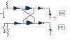
If correct, the moderator pushes a "RIGHT" button that causes the enabled counter to add one count.
If incorrect, the moderator pushes a "WRONG" button that causes the enabled counter to subtract one count.
The RIGHT and WRONG buttons go to both counters but only the "enabled" counter responds.
A four-input AND or NAND gate on the output of each counter could be AND'd with the enable lines so the counter will not decrement to 9 if the count is at zero.

A simpler version would not have a "WRONG" down-count function, just no point for a wrong answer.

All this said, it's been years and years since I built counters and display converters from discrete logic gates. Maybe someone can jump in with more recent experience.

Ken
 
Last edited:
I'm not familiar with that text. Are you only allowed to use AND, NAND, OR, NOR, XOR, and XNOR gates? Can you use S-R, D, and JK flip flops...without having to build them from basic gates?

Ken
 
I have figured out a solution to do this,i will try that,if that doesnt
work,then i will take your help,In the mean time.Thank You very
much for your kind help ,I really appreciate it..:)
 
probably u can use two counters. one for correct answers and one for wrong answers... then you can subtract both result at last to get the final scoring....
 
Status
Not open for further replies.

New Articles From Microcontroller Tips

Back
Top