Continue to Site

Welcome to our site!

Electro Tech is an online community (with over 170,000 members) who enjoy talking about and building electronic circuits, projects and gadgets. To participate you need to register. Registration is free. Click here to register now.

  • Welcome to our site! Electro Tech is an online community (with over 170,000 members) who enjoy talking about and building electronic circuits, projects and gadgets. To participate you need to register. Registration is free. Click here to register now.

Question About Stepper Motor Vsupply and Microcontroller Vsupply

Status
Not open for further replies.

tehipwn

New Member
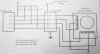
Hello. I am interfacing a 12V stepper motor to my 5V microcontroller. I have this image from a textbook of mine, which is attached. As you can see, it says to use one power supply for the ULN2003 and motor and another for the 8051. My question is exactly what does this mean?

I am in the process of building a 120VAC/DC converter using the standard transformer, bridge rectifier, and a smoothing capacitor. The output of the capacitor will be approximately 12V with VA rating of the xfmr large enough to supply current to both the motor and control circuitry. I then wanted to use a switching regulator buck converter to convert the +12V to +5V with 300mA Iload capability to power my 8051.

Can I use this 1 transformer, 2 voltage level design to power both my 8051 and my motor? Or do they need to be totally isolated, meaning I need 2 transformers with the 12V and 5V turns ratios?

If this method will work, I am having trouble finding a 12V linear regulator (3 terminals) with over 1.5A capability, any suggestions?

Thank you in advance everyone.
 

Attachments

  • stepper_motor.jpg
    stepper_motor.jpg
    26.2 KB · Views: 299
Last edited:
The ideal solution is two power supplies; 5V one for the uC, 12V for the stepper, with opto-isolation for the logic drive.
Second best is two power supplies, common ground connection, without opto-isolation.
Third best is one 12V power supply, with a linear regulator to create the 5V, common ground.

Preventing inductive spikes from the stepper getting into and interfering with the uC operation has generated hundreds of posts on these forums. If you start with option 3, you will learn more than you ever wanted to know about common grounds, single-point grounds, ground-loops, bypassing, common-mode noise, shielding, bypassing, etc...
 
Last edited:
Okay, that's what I was afraid of. So, my single transformer idea is out. Should I now proceed to buy 2 transformers (probably of equal turns ratios, lets says 120Vrms to 15Vrms, use 2 diode bridges and capacitors. Then for the 12V motor supply, use a simple linear regulator to keep it at 12V. And for the microcontroller, use the aforementioned buck converter to make it down to 5V? Thanks
 
You will probably need a lot more power at 12 V than at 5 V, so you will want totally different transformers for the two supplies, as both the turns ratios and powers will be different.

Mains transformers are normally marked with output voltage not turns ratio.
 
Okay thanks. So I'll buy 2 different transformers. Could I get your inputs on which transformers any of you have used previously?

My idea is that I'll input 120Vrms to both xfmrs. Accounting for approximately 1.4V drop across the bridge rectifier, then another 1.5V drop for a linear regulator, for the 12V I should buy a 12+1.4+1.5=14.9 + 10% ripple voltage for approximately 16.5V???

Same goes for the 5V supply, so a 9.5V output xfmr???

If my 12V supply is only going to supply a single stepper motor needing less than 1 amp, does it even need a linear regulator??? If so, would say a 12V 1A linear regulator be ideal?

Thank you all so much for the extremely quick and helpful advice!
 
Dont overlook something as simple as a 5V regulated wall-wart for the uC supply. They usually only need 50 to 200mA. I'm playing with a TI MSP430 right now that can do a lot of DSP-like computing on ~2mA.
 
Thanks again for all the very helpful replies. I have simulated the 120VAC to 5VDC, 1A design and it seems to be good. Using a LT1176 in the buck configuration. An attachment is supplied showing the circuit and waveforms. This supply will be used for my microprocessor and some other low current circuitry.

However, I am having trouble coming up with a design for my regulated 12V, 1-5A (doesn't really matter because I haven't bought the motor yet) supply. The supply load will be a single stepper motor (12V 1-5A). I have tried using the circuit shown in the second attachment. I couldn't find anywhere online how to control the output voltage on the LT1084. All the examples were for Vout of 5V. Could anyone help on what I need to adjust to regulate 12V and supply a stepper motor?

The second attachment shows Vin, Vout, and Iout.

Thanks again.

EDIT:

I'm thinking about buying this stepper motor for the high holding torque.
**broken link removed**

Is that a relatively good deal?
 

Attachments

  • 120V_to_5VDC_1A_Regulated_PSU.pdf
    74.8 KB · Views: 173
  • 120V_to_12VDC_Regulated_PSU.pdf
    66.6 KB · Views: 202
Last edited:
Why not salvage or buy a ATX computer power supply? It will have more than enough amperage and gives both 5V and 12V.
 
Well this is for powering my senior design project, so I can't use off the shelf equipment. My project is automated conveyor belt sorting application. I got the 12V linear regulator working...had the resistors hooked up wrong. I'll post the schematic soon for completeness.
 
Why not salvage or buy a ATX computer power supply? It will have more than enough amperage and gives both 5V and 12V.

Yes, but this open's Pandora's Box due to the common ground between the 5V and 12V supplies inside the ATX box.
 
Yes, but this open's Pandora's Box due to the common ground between the 5V and 12V supplies inside the ATX box.

I have everything about ready to order for the two separate supplies. When I hook up the 2 separate transformers to my mains 115VAC wall outlet, can the 2 primaries of the transformers share a common bus and cord/plug?

Thanks.
 
Yes. Both primaries can be downsteam of a common ON-OFF switch. It is no different than using a single transformer with two isolated secondaries.
 
Yes. Both primaries can be downsteam of a common ON-OFF switch. It is no different than using a single transformer with two isolated secondaries.

Oh, so I should have just bought a single transformer with 2 secondary windings to save probably about $15 and space even though they're two totally different VA ratings?

Here is my design and part numbers. Hopefully it works because I have put a lot of effort into it.

If anyone sees any blaring errors I welcome any criticism (no matter how small). I will post the LTSpice IV files if anyone asks.

Thank you!
 

Attachments

  • 12V_and_5V_PSU_Designs.pdf
    396.8 KB · Views: 630
Isn't the 1A @5V a bit of overkill for a uC that likely needs ~50mA? If there are analog sensors and A/D stuff going on in the uC, I wouldn't use a switcher there. I would have used a linear regulator on the 5A P.S., and the switcher on the 12V one.

How is your heatsinking on the 12V regulator?
 
I just chose 5V @ 1A because that's the ratings of the wall-xfmr that came with my uC programming board (I have the power supply already...haha). And I just wanted exposure to designing both forms of regulators and I thought the uC and digital circuitry warranted the more sophisticated supply. I guess that makes sense. For the linear regulator I tried picking a xfmr secondary voltage as close to the required approximately 14V input needed for the regulator to function, to minimize energy loss. I spec'd out a fanned aluminum heat sink for the 12V regulator and went through the thermal calculations in the datasheet. It turned out good at around 125 degrees celcius at 80 degrees ambient. The calculations are in the PDF. Here's a picture of the heat sink.

**broken link removed**
 
Last edited:
Status
Not open for further replies.

Latest threads

New Articles From Microcontroller Tips

Back
Top