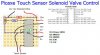
Solenoid looks fine but... Looks like you are powering your PIC with 12 volts so not good.
")
The bypass looks just fine. The trick is as close to your PIC power pin as possible.
Wooops... I fixed that on my layout to avoid confusion. Copy/Paste fail! Thanks!
As to the base resistor, try giving
this link a read. The first few post cover it well. So yes, the load makes a difference.
I'm trying to wrap my head around the equation offered in that thread. It reads:
Ib = (Vparallelout - Vbe) / Rb
My guess at the variables here:
Ib = Current at base? (20mA from chip?)
Vparallelout = Voltage at collector? (12v?)
Vbe = Vbe (sat) max value on 2N2222 datasheet? (2v?)
Rb = The base resistor value i am looking for?
I don't think that can be right because I don't have any information on the load (solenoid) in there. Can you clarify the variables for me?
How many solenoids? That depends on how you configure them. Meaning if you wanted to fire 4 or 6 or whatever all at the same time then you would consider a larger transistor and parallel your loads (solenoids) or likely use a MOSFET as a switch to handle the high load of all the solenoids. However, if you want to fire your solenoids for example sequentially (at different times) from your PIC then you need to figure the base emitter current you draw for your transistor(s) and work from there. I guess we could say it's all about current.
Well, 5-8 solenoids total, each able to fire at any time. All connected solenoids might be active at the same time. I thought I would need a MOSFET for each solenoid? The attached layout was me working on the assumption that 4 is my max.
EDIT: Note IC1 & IC2 are actually just 1 IC... Picaxe 18M. The software i'm using doesn't support 18 pin ICs so I used two next to each other to simulate 18 pins.
Thanks again for all your help!!
-Scott