Continue to Site

Welcome to our site!

Electro Tech is an online community (with over 170,000 members) who enjoy talking about and building electronic circuits, projects and gadgets. To participate you need to register. Registration is free. Click here to register now.

  • Welcome to our site! Electro Tech is an online community (with over 170,000 members) who enjoy talking about and building electronic circuits, projects and gadgets. To participate you need to register. Registration is free. Click here to register now.

Question about connecting digispark pin P1 to led driver board with PWM pin...

Status
Not open for further replies.

hoghunter

Member
I have an Attiny digispark controller with an LED fade sketch loaded. The sketch does work properly on the breadboard with a small 20ma led and a 2N3904 transistor setup for the PWM switching. However, I am burning transistors when lighting the (3) 3w high power leds I will ultimately be using.
The LED pin is P1. I also have an LED driver board like the one below. I want to connect pin 1 directly to this board to control the PWM. I need some guidance on how to connect any and all wiring to the driver board. I have tried a few different ways, but see no PWM changes when sketch is run. I have searched for diagrams, etc.. and have found nothing specific to the PWM connection on the driver board. A description is included below also:
Please help. Thanks.

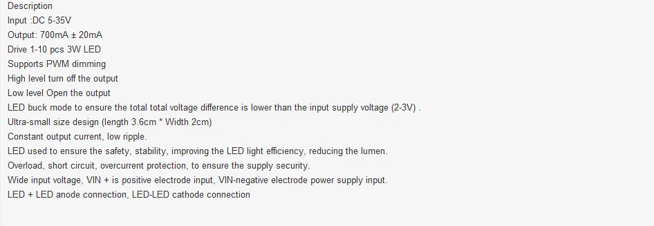
mYv1e6kk-z45BXvOs6xmFFg.jpg
HTB1a1AdLXXXXXXhXpXXq6xXFXXXg.jpg
 
A link to the actual module would help, especially if there is a data sheet.

Mike.
 
Here is the current configuration. After more reading last night, it appears I need to hold the PWM pin on the driver module HIGH, which would stop current flow, then send the PWM pulse from the digispark's pin 1 to the LED driver module PWM or GND pin to bring it LOW, which allows current to flow. Maybe the 2N3904 should still be incorporated somehow, along with a 'pull up' resistor? Considering the low PWM voltage from pin 1 on the digispark, the transistor should be ok?
As I am new to this, I have gone as far as I can at this point and I do not want to fry my circuit... thanks for your help.

This is what I have at this point:

upload_2017-8-17_7-54-40.png
 
Remove the transistor and connect Driver pin4 to GND.
Connect DS Pin1 PWM output to PWM input on the Driver.
Connect the Driver PWM GND to the same/common GND as the Digispark.
 
The 2n3904 will do nothing except keep the RCD-24 from working.

Back to basics: According to this data sheet:
if the led driver is to be pwm'ed directly using pin 3, then the pwm pulse train frequency should be 200Hz or less. The PWM produced by the Arduino library is ~500Hz (too high), so you could directly drive pin 3 if you write your own bit-bang code to generate a pwm signal out of the Digispark at about 100Hz.

Alternatively, use the analog input to the led driver and the existing PWM function in the Arduino library, but put a low-pass filter between the Digispark pwm output, and the led-driver's analog input pin 2.
 
Remove the transistor and connect Driver pin4 to GND.
Connect DS Pin1 PWM output to PWM input on the Driver.
Connect the Driver PWM GND to the same/common GND as the Digispark.

The connections are ok, but this may not work due the reason in post #7.
 
Last edited:
Light bulb !! Could it be as simple as changing my sketch
Remove the transistor and connect Driver pin4 to GND.
Connect DS Pin1 PWM output to PWM input on the Driver.
Connect the Driver PWM GND to the same/common GND as the Digispark.

Yes, I tried that. The leds illuminated fully and were not effected by the PWM signal coming from Pin 1 on the DS.
 
The 2n3904 will do nothing except keep the RCD-24 from working.

Back to basics: According to this data sheet:
if the led driver is to be pwm'ed directly using pin 3, then the pwm pulse train frequency should be 200Hz or less. The PWM produced by the Arduino library is ~500Hz (too high), so you could directly drive pin 3 if you write your own bit-bang code to generate a pwm signal out of the Digispark at about 100Hz.

Alternatively, use the analog input to the led driver and the existing PWM function in the Arduino library, but put a low-pass filter between the Digispark pwm output, and the led-driver's analog input pin 2.

Mike,
The module that represents my driver board was a random choice. It actually has the XL4001E chip:

https://www.alldatasheet.com/datasheet-pdf/pdf/763180/ETC2/XL4001E1.html
upload_2017-8-17_10-31-31.png
 
Last edited:
Mike,
The module that represents my driver board was a random choice. It actually has the XL4001E chip:

https://www.alldatasheet.com/datasheet-pdf/pdf/763180/ETC2/XL4001E1.html
Stupid damn data sheet. It never specifies the allowed maximum frequency for the PWM input pin!

I would connect a signal generator (TTL output) to the PWM input of the driver board, and see at what frequency it begins working...

I predict that the driver board will not follow the PWM input if the frequency is greater than ~100Hz, meaning that you cannot use the Arduino PWM function directly. You will have to write your own PWM routine, which is almost trivial to do...
 
Mike,

As my fading sequence sketch takes the leds from off to on (0-255), the fades them back off (255-0), I assume I will need to modify (invert) my sketch also to have the proper on/off fading as the driver's PWM function is reverse logic? High=off, Low=on ?
 
Yes, and the 100Hz problem is as simple as :

pin=some pin; //a contant.
Per=1e6/PwmFreq; //a constant.
x=3900; //a variable related to duty cycle such that 0<x<Per

Loop while ... //some kind of loop...
digitalwrite(pin,high);
delaymicroseconds (x);
digitalwrite(pin,low);
delaymicroseconds(Per-x);​
end loop;
 
Last edited:
Stupid damn data sheet. It never specifies the allowed maximum frequency for the PWM input pin!

I would connect a signal generator (TTL output) to the PWM input of the driver board, and see at what frequency it begins working...

I predict that the driver board will not follow the PWM input if the frequency is greater than ~100Hz, meaning that you cannot use the Arduino PWM function directly. You will have to write your own PWM routine, which is almost trivial to do...

  • I was looking for that also to see if 500Hz would work, but did not find it either.
  • I will search for how to connect a signal generator (TTL output?), and go from there....
  • I already have a PWM routine written that does the fading on my leds. Will I need to modify it possibly to control the Hz frequency? Is that what you mean?
Thanks for your help on this !!
 
You can use the digispark as a TTL frequency generator by just changing the period in the code snippet in post #14. Changing 10000 (10ms) to 5000 (5ms) would make the frequency 200Hz, and so on...

There seems to be an upper limit to the argument to the delaymicrosec() function. Read the Arduino library help page.

I'll work on that..... thanks again. I'm in learning mode for sure.

Just so I understand, I assume that a delay of 2000 (2ms) would get you 500Mz? I will try 200Hz
(5ms) first and go down from there until I see PWM activity.....
 
Last edited:
The frequency is determined by the sum of the two delays [x+(Per-x) ] = [Per+x-x] = Per, so to get a frequency of 200Hz, you need a period of 1/Freq = 1/200 = 0.005s = 5ms = 5000us

Say you wanted 25% duty cycle, so x=0.25*5000 = 1250, so the first delay would be 1250us, and the second delay would be 5000-1250 = 3750us.

Yes, I understand.:) It makes sense.
 
Status
Not open for further replies.

Latest threads

New Articles From Microcontroller Tips

Back
Top