Electro Tech is an online community (with over 170,000 members) who enjoy talking about and building electronic circuits, projects and gadgets. To participate you need to register. Registration is free. Click here to register now.
Welcome to our site! Electro Tech is an online community (with over 170,000 members) who enjoy talking about and building electronic circuits, projects and gadgets. To participate you need to register. Registration is free. Click here to register now.
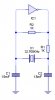
Could somebody please show me how i can use a quartz crystal to create a high pulse every second. i came up with the following circuit. but i can't get the values right. :?
:lol:
The quartz parallel oscillator is good to make in high frequence, say over 100KHz. With your 32.768KHz cristal is dificult to make a parallel oscilator because you need very high resistor in R2 place over 20M and a good qquality cristal(with low serial resistance at resonance). The capacitors from your schematic must be in range of 10...50 pF for oscillator work.
But a better idea for low frequency cristals is serial oscillator as in follow picture. The CMOS inverters must be unbuffered type in both cases of parallel and serial OSC.
If you increase capacitator value, the circuit becames more stable, but has a higher startup time. Isn't it? what about resistors??
And.. sometimes I read "oscilating at its natural resonant frequency". Is it possible not to do so?
The capacitor(in serial-qz) is only for signal transfer and is calculate to make a good coupling relative to input impedance of inverter 2.
The resistors make the inverters to work in linear region as linear amplifiers. This resistors impose the input impedance of inverters equal with resistor value divided at voltage amplifier of inverter so the impedance is lower than resistor value.
The oscillator will work with a resistors and capacitor values in a wide range but when resistors increase the stability decrease. This happen because the Qz work here as a RLC serial circuit, at resonance the Qz impedance have a minimal value and entire loop transfer(through I1-C1-I2-Qz) is over 1. At other value of freq the Qz impedance is very high and the loop transfer become under 1, but if the input impedance of I1 is high the parasitic capacitance of Qz will inject more easy the signal in I1 input and the oscillator have tendency to oscillate on other freq than the Qz resonance. This problem become worst on high freq. so the serial osc. is not good for high freq.
This site uses cookies to help personalise content, tailor your experience and to keep you logged in if you register.
By continuing to use this site, you are consenting to our use of cookies.

")
