Continue to Site

Welcome to our site!

Electro Tech is an online community (with over 170,000 members) who enjoy talking about and building electronic circuits, projects and gadgets. To participate you need to register. Registration is free. Click here to register now.

  • Welcome to our site! Electro Tech is an online community (with over 170,000 members) who enjoy talking about and building electronic circuits, projects and gadgets. To participate you need to register. Registration is free. Click here to register now.

Quadrature Encoder Debounce in ASM

Status
Not open for further replies.
I suggest that "quadrature" is a subset of Gray Code.

Two bits, modulo 4

Please see my attachment.

JimB

View attachment 92362
Ok! I concede!! But just don't use a gray wheel decoder or it will just count up and down repeatedly!!!
 
But just don't use a gray wheel decoder or it will just count up and down repeatedly!!!

That is a fair comment.
I guess that Gray codes give an absolute position, whereas the Quad code gives a relative position and is often used in conjunction with an index pulse to define a fixed position.

The only place where I have seen Gray codes used was in a remote display for a tank* level measurement system.

* A BIG oil storage tank.
If I remember correctly it had a float on the end of a steel wire.
As the level went up/down, the steel wire turned around a drum which drove allsorts of gears and numbers for a local display, and a GrayCode disc for the remote display.

JimB
 
Ok! I concede!! But just don't use a gray wheel decoder or it will just count up and down repeatedly!!!
Gray wheel decoder is just direction and count pulse just like Quadrature. Not up and down, rather up OR down, Or CW or CCW. Or in the case of stepper motors Step in/out from Direction and step. It is a reversible process used everywhere , even wind direction and anenometers.
 
Last edited:
Hello

can you somebody help to make the hex file from this code?

Code:
#include <stdint.h>
#include <avr/pgmspace.h>
#include <avr/io.h>
#include <avr/interrupt.h>
#include <avr/wdt.h>

#define F_CPU 12000000
#include <util/delay.h>

#define DEPRESS_TIME    1

#define sbi(sfr, bit)   ((sfr) |= _BV(bit))             // Set bit
#define cbi(sfr, bit)   ((sfr) &= ~(_BV(bit)))          // Clear bit
#define xbi(sfr, bit)   ((sfr) ^= _BV(bit))             // Flip bit
#define rbi(sfr, bit)   (((sfr) >> (bit)) & 0x01)

volatile uint8_t pcIntCurr = 0;
volatile uint8_t pcIntLast = 0;
volatile uint8_t pcIntMask = 0;

volatile uint8_t timer0_ovf = 0;
volatile uint8_t time_rot = 0;

void doInt();

int main() {
cbi(DDRB, PCINT2);
cbi(DDRB, PCINT3);

TIMSK = (1<<TOIE0);                   // Eable timer overflow for Timer0
TCNT0 = 0x00;                         // Set Timer0 to 0
TCCR0B = (1<< CS02) | (1<<CS00);      // /1024 prescaler

PORTB |= (( 1 << PCINT2 ) | ( 1 << PCINT3 )); //turn on pullups
PCMSK |= (( 1 << PCINT2 ) | ( 1 << PCINT3 )); //enable encoder pins interrupt sources
sei();
GIMSK |= ( 1 << PCIE ); //enable pin change interupts

DDRD |= ( 1 << PD4 );
DDRD |= ( 1 << PD5 );
DDRD |= ( 1 << PD6 );

sbi(PORTD, PD6);
_delay_ms(1000);
cbi(PORTD, PD6);

for (;;) {

if (!time_rot) {
cbi(PORTD, PD4);
cbi(PORTD, PD5);
}

if (pcIntMask)
doInt();
}
}

void doInt() {
xbi(PORTD, PD6);

if (rbi(pcIntCurr, PCINT2) == 0 && rbi(pcIntCurr, PCINT3) == 0 && rbi(pcIntMask, PCINT2) ) {
cbi(PORTD, PD5);
sbi(PORTD, PD4);
time_rot = 5;
} else if (rbi(pcIntCurr, PCINT3) == 0 && rbi(pcIntCurr, PCINT2) == 0 && rbi(pcIntMask, PCINT3) ) {
cbi(PORTD, PD4);
sbi(PORTD, PD5);
time_rot = 5;
}

pcIntMask = 0;
}

ISR(TIMER0_OVF_vect) {
timer0_ovf++;

if (time_rot) {
time_rot--;
}
}

ISR(PCINT_vect)
{
pcIntCurr = PINB;
pcIntMask = pcIntCurr ^ pcIntLast;
pcIntLast = pcIntCurr;
}


[code]

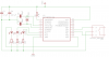
thank you and this is the circuit I have[ATTACH]92380[/ATTACH] [ATTACH=full]92380[/ATTACH]
 

Attachments

  • rotaryencoder_schematic.png
    rotaryencoder_schematic.png
    9.3 KB · Views: 314
Hello Friends

Thank you for all the reply...

I got this circuit from internet..Its completely working, I tested...


Encoder Tester.GIF

I atteached the hex file too...


Thank you
 

Attachments

  • Manoj.rar
    973 bytes · Views: 423
This is interesting:
from : BobW


Code:
    Code (asm):

    ; Encoder service routine
    ; for midrange PIC 12F, 16F...
    ; Inputs:
    ;    PortA,0 - Phase A input (position critical) - IOC
    ;    PortA,1 - Optional Index input
    ;    PortA,2 - Phase B input (position critical) - IOC
    ;
    ; Encoder variables:
    ;    CountH, CountL - High and Low byte of Encoder count
    ;    SaveA - Previous state of Phase A input
    ;
    EncdrSvc
        rrf portA,w      ;load, shift and save phase A
        rlf SaveA,f      ;new Phase B and “delayed” Phase A are now aligned
        xorwf SaveA,w    ;XOR to calculate direction
        andlw 0x02       ;mask off all but direction value which is either 0 or 2
        subwf CountL,f   ;subtract 0 or 2 from count depending on direction
        btfsc status,c
        incf CountH,f
        incfsz CountL,f  ;then add 1 to adjust the 0/+2 increment to +/-1
        decf CountH,f

It is based on the fact that once a change of state of either encoder output (A or B) is detected (by means of the IOC—Interrupt On Change setting), then the direction of rotation can be determined by XORing the current state of one output with the previous state of the other output. This fully decodes every state transition, giving the maximum possible resolution. Note also that the PIC inputs are arranged for maximum efficiency. The above code doesn't include the standard ISR preamble and postamble, for saving and restoring the W and Status registers, which is still required .
 
Status
Not open for further replies.

Latest threads

New Articles From Microcontroller Tips

Back
Top