Continue to Site

Welcome to our site!

Electro Tech is an online community (with over 170,000 members) who enjoy talking about and building electronic circuits, projects and gadgets. To participate you need to register. Registration is free. Click here to register now.

  • Welcome to our site! Electro Tech is an online community (with over 170,000 members) who enjoy talking about and building electronic circuits, projects and gadgets. To participate you need to register. Registration is free. Click here to register now.

Pwm

Status
Not open for further replies.
Hey everyone.

I just received some RGB LED's from eBay and would like to start a PWM project with a PIC.
I have never used a PWM before so I would like to start at the very basics...

So my question is, I would like to know if it is possible to make a PWM using an RC oscillator and some more components?

Jake.
 
Depends on if you want to do it "open loop" (which you can do with a 555), or if you want to do it "closed loop" where you measure the actual current through the LEDs, and adjust the pulse width on the fly to get a specified current.
 
I think it can be done directly with the PIC chip with one command. Check the data sheet.
Of course it can, but I would like to know if I can do it without a uC.
Just so I can observe the output with an osciloscope and see what effect it has on one led.
Without having to program pic...
 
Last edited:
So my question is, I would like to know if it is possible to make a PWM using an RC oscillator and some more components?
The usual way to achieve PWM control is to generate a sawtooth or triangle signal. Then feed this signal into the positive input of an comparator. On the negative input, you aply the control voltage, wich should have any value between the sawtoot signals most positive and most negative value.
 

Attachments

  • PWM.png
    PWM.png
    34.8 KB · Views: 291
Last edited:
The only reason for doing it Grossel's way is if you are building a feed-back control loop, in which case the control voltage pot comes from a summing amplifier instead. If all you want to do is twist a pot, and thereby change the pulse width, use a 555 wired like this.
 

Attachments

  • PWM555.png
    PWM555.png
    61.9 KB · Views: 315
Yeah yeah I was thinking more of a twist pot type setup, and having never used comparators before either, I will give Mikes suggestion a go with the 555.

Many thanks.
 
Everyone is trying to make the whole situation more complex than it is.
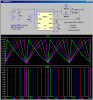
PWM is simply a way of controlling the speed of a motor or the brightness of a LED or globe by delivering energy to it as a percentage of the maximum.
This percentage is delivered as a short pulse in which the delivering element (the driver transistor is fully turned on) and then it is fully turned off for the remainder of the cycle.
In this way the transistor is in one of two states in which it is dissipating the least energy and this makes the concept very efficient.
In addition, it allows the motor to create considerable torque, even though the motor will be revolving at a very low RPM.
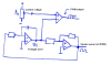
When it comes to driving a LED, it will be illuminated at a high brightness for the short period of time and our eyes will detect this high brightness, even though it is consuming considerably less energy than if it were illuminated by a steady voltage (current). This means a LED must be driven at a very low on-percentage to actually see a reduction in brightness. The following circuit can be used for a motor or LED and the FET can be replaced with any type of transistor as shown in the second and third circuit. You can create a variable mark-space circuit with one gate of a 74c14 and a few components.

**broken link removed**

**broken link removed**
 
Last edited:
Of course it can, but I would like to know if I can do it without a uC.
Just so I can observe the output with an osciloscope and see what effect it has on one led.
Without having to program pic...

Oh sorry. I "assumed that since you said "I just received some RGB LED's from eBay and would like to start a PWM project with a PIC" that you intended to use one! ... LOL. Silly of me.

Have fun
 
That's alright raxlan, I probably could have worded that a little better, thanks for your input.

And thanks Grossel mikeml & Collin, that will come in handy
 
Status
Not open for further replies.

Latest threads

New Articles From Microcontroller Tips

Back
Top