can anyone post a PWM circuit based on the 555?
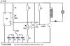
I have found thi one:
https://www.rmcybernetics.com/projects/DIY_Devices/homemade_signal_generator2.htm
1) Can I use 12 VDC in the circuit posted in the link?
2) In the right end of the circuit I see 3 wires: the output (middle), the ground (low part) and other in the upper part that I don't know where to connect it.
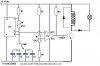
Last edited:
")