Continue to Site

Welcome to our site!

Electro Tech is an online community (with over 170,000 members) who enjoy talking about and building electronic circuits, projects and gadgets. To participate you need to register. Registration is free. Click here to register now.

  • Welcome to our site! Electro Tech is an online community (with over 170,000 members) who enjoy talking about and building electronic circuits, projects and gadgets. To participate you need to register. Registration is free. Click here to register now.

PWM Output to Analog Audio

Status
Not open for further replies.

Suraj143

Active Member
I'm generating an alarm sound from PWM frequency. PWM frequencies are 1Khz & 1.4KHz.Its just like two tone police siren.
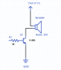
I want to drive an 8 ohms small speaker from this PWM output.For the time being I'm driving the speaker as in the attachment.
Is their any modifications to get smoothed audio quality?Do I need a low pass filter?
 

Attachments

  • Speaker Drive.png
    Speaker Drive.png
    39 KB · Views: 283
PWM frequencies are 1Khz & 1.4KHz
Are those the modulation frequencies or the pulse repetition frequencies?
Your speaker drive arrangement has constant DC through the speaker. That will cause distortion. I'd consider using a push-pull drive instead.
 
To get both sides of the wave. replace the transistor with a H-bridge. You will have to modulate your output at a much higher frequency, at least 10x using a sine wave look up table. The higher the frequency the PWM the less filtering. 20 kHz would be out of audio range. https://en.wikipedia.org/wiki/Class-D_amplifier


You might search for piezo buzzer (just power) and/or piezo speaker (You have to create the sound) and follow their guidance.

Or, you can purchase a dual tone buzzer: **broken link removed**

I have a "dip" at 2600 Hz in my hearing and I made a "plug-in" buzzer at a single frequency using a Sonalert module. I got one that could be volume controlled mechanically and runs at like 120 db. If I really want it to wake me, I need the module pointing at me.
 
To get both sides of the wave.

While the schematic in post #1 has several...issues, it is entirely capable of "get(ting) both sides of the wave". I'm not a big fan of dangle biasing, but that doesn't matter since he would be driving the transistor between saturation and cutoff.

Also,I think the OP is calling his signal PWM because it seems that way to him semantically, or because it is coming from a PWM function within the uC, without knowing the details of what the industry standard use is. My guess is that he has a square wave output at two fundamentals, not true PWM.

ak
 
A small speaker driven by those DC pulses from the single transistor probably has its voice coil slammed up against its magnet on each cycle of the sound. That would sound even raspier than the squarewave buzz.
 
Hi thanks for the replies guys.

Yes I'm generating a PWM frequency @ 50% duty cycle from a PIC micro 5V supply.It comes like this.

1)out 1Khz
2)play it 1 second
3)change it to 1.4Khz
4)play it 1 second
goto step 1

What about the transistor..!! it is just a basic transistor.Do I need an audio transistor like C1815?

The above works loud.But I need to make it more smoothly.Driving a 8 Ohms/0.5W speaker.
 
With a power source of +5 V and GND, look into something based on the LM386 or TDA7052. Very common small power amplifiers, with very low cost modules available from China if you don't/can't solder. Both of these will distort with the full amplitude signal you have, but a simple RC filter/attenuator can be added to smooth out the square wave signal to something closer to a sinewave, closer to a pure tone. Does this sound like what you want?

ak
 
You have squarewaves, not PWM.
If your transistor turns on completely then the speaker gets almost 5V across it and its current is 5V/8 ohms= 625mA that will destroy most little transistors. A 2SC1815 has a maximum allowed current of only 150mA.
The speaker is fed 5V at 625mA for half the total time so it gets (5V x 625mA)/2= 1.56W in DC pulses, not AC audio so the 0.5W little speaker will also be destroyed.

But actually the 1k base resistor allows a base current of only 3mA to 4mA so the transistor will conduct a saturation current into the speaker of only 30mA to 200mA.
 
I don't know how much filtering you need.
Here I connected a 0.22uf cap from the C to B of the transistor.
I did not measure how hot the transistor will get. Watch out. It will heat some.
upload_2015-9-23_13-17-9.png
 
Yes I need a small filtering which will make affect closer to a pure tone.

Ron thanks for the design.Small question.Is that a ceramic capacitor or a polarized electrolytic capacitor?
Later I'm going to change its duty cycle to adjust the volume, will it cause with that capacitor?2N3019 is hard to find, I will use an alternative.
 
The capacitor could be two 0.1uf caps in parallel.
I would use ceramic not electrolytic.
I used a 2n3019 because I had one in the spice program. I did not have what you have.
 
According to Fourier Analysis, a square wave is actually a combination of an almost infinite colleection of sine waves, a fundamental and many harmonics. The more harmonics you eliminate or reduce, the more the wave sounds like the pure tone of the fundameental sine wave. But eliminating harmonics removes energy from the wave, decreasing its apparent loudness. A 1 V peak-to-peak square wave has an RMS value of 1 V. For a sine wave to have the same RMS value, the peak-to-peak value is 1.4 V.

ak
 
Hi thanks for the clear explanation.that explains most of the stuff.

I replaced the D400 with a 2N2222 transistor.now the sound is sharp & very nice to hear.i removed that filter caps too.

I am happy with the result.
 
Status
Not open for further replies.

Latest threads

Back
Top