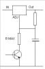
It will not work!!! You need to set your max voltage with the normal circuit (a resistor from out to sense and a resistor to GND) and then put a transistor in the GND line.
Then put a BIG cap from sense to GND, the value is determined by the response time you need.