Continue to Site

Welcome to our site!

Electro Tech is an online community (with over 170,000 members) who enjoy talking about and building electronic circuits, projects and gadgets. To participate you need to register. Registration is free. Click here to register now.

  • Welcome to our site! Electro Tech is an online community (with over 170,000 members) who enjoy talking about and building electronic circuits, projects and gadgets. To participate you need to register. Registration is free. Click here to register now.

PWM motor with parallel BJT

Status
Not open for further replies.

Fercho7

New Member
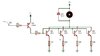
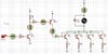
Hello forum. I am designing a 90v 4.5A pwm. In a preliminary test I used three tip35c directly with an arduino with the motor without load and it works. Now to add load I want to make a good circuit to manage four tip35c, for that I took the minimum gain in the datasheet as 15 and each transistor with 1.125A of maximum current so the base current is 75mA. Could I use a single PNP transistor to manage all four tip35s or do I have to use one PNP transistor for each tip35? Attached is the circuit that I had planned to do.
I thank you for your collaboration and other recommendations.
 

Attachments

  • PwmCircuit.JPG
    PwmCircuit.JPG
    50.4 KB · Views: 527
The current gain hFE on a datasheet is used when a transistor is used as a linear amplifier with plenty of emitter-collector voltage.
A transistor used as a switch (like you are doing) must saturate and the datasheet says then its base current must be 1/10th its collector current.
Then the total base current must be 0.45A and the base current of the 2n4403 must be 45mA. One 2N4403 will be fine.
re-calculate the 10 ohm resistor value.
Can your signal source produce 45mA?
Why not use a logic level Mosfet?

thanks for your reply.
Where can I find this 1/10 ratio on the datasheet, does it have a particular name? or is it a condition for all transistors in saturation?
Actually my signal source does not produce 45mA, it is an arduino, I made my assumption with 50 hfe on the 2N4403, I did not know the 1/10 ratio.
About the logic level mosfet, I hadn't thought about that, what is a good reference?
In the past, I used a traditional mosfet, the irf540. I put four irf540s in parallel and activated them with an ir2110 and 12v, the circuit worked fine with a small motor and with less voltage, but at 90v the circuit stopped working. So since the tip35c worked for me in the pretest, I stopped researching the mosfets.
 
The datasheet of all transistors say its saturation specs.
An IRF540 needs a 10V gate-source voltage to fully turn on.
An IRL540 (see the "L"?) is "logic level" and needs a Vgs of 5V to fully turn on.

A transistor or Mosfet gets too hot if it has high supply voltage and high load current but it is only partially turned on.
 

Attachments

  • 2N4403 saturation.png
    2N4403 saturation.png
    35 KB · Views: 218
Where can I find this 1/10 ratio on the datasheet, does it have a particular name? or is it a condition for all transistors in saturation?
It's a condition to achieve transistor saturation.
See clip from datasheet below:
Notice that the base current is 1/10 of the collector current to assure good saturation.

1619972687051.png
 
Then the total base current must be 0.45A and the base current of the 2n4403 must be 45mA. One 2N4403 will be fine.
re-calculate the 10 ohm resistor value.
Can your signal source produce 45mA?

It's a condition to achieve transistor saturation.
See clip from datasheet below:
Notice that the base current is 1/10 of the collector current to assure good saturation.

@audioguru @crutschow Thank you very much for your help

I have planned this circuit with the tip35 and resistance values that I can easily find or complete in the store. I added a 2n2222 to handle the approximate 45mA in the base current of the 2n4403. Do you think this circuit is correct? o How can I improve it?
 

Attachments

  • PwmCircuit.JPG
    PwmCircuit.JPG
    182.5 KB · Views: 223
The TIP35C can handle 25Amps (40 peak). Why are you adding the complexity?
Make sure you use a TIP35C, the A and B versions cannot handle the 90v supply you plan to use for your motor.
 
Status
Not open for further replies.

New Articles From Microcontroller Tips

Back
Top