Continue to Site

Welcome to our site!

Electro Tech is an online community (with over 170,000 members) who enjoy talking about and building electronic circuits, projects and gadgets. To participate you need to register. Registration is free. Click here to register now.

  • Welcome to our site! Electro Tech is an online community (with over 170,000 members) who enjoy talking about and building electronic circuits, projects and gadgets. To participate you need to register. Registration is free. Click here to register now.

PWM microprocessor signal

Status
Not open for further replies.

2PAC Mafia

Member
Hi guys,

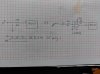
I´ve been repairing a board which controls a motor through a PWM signal. It had damaged the IGBT, the IR2127 driver and some resistors.

The problem is after replacing all components the board is still failing because the microcontroller in charge of sending the PWM signal to the IR2127 driver sends a PWM signal from 2,5V to 5V instead of going to 0V to 5V. I was thinking about remove the DC filtering with a 100nF cap. Like that I get 2V PWM signal but it seems is not enough to start the IR2127, I don´t have any output.

Then I wanted to amplify the signal with a LM2903. The problem is at the output I have exactly the same signal, not amplified.

Where is my fault? I attach a diagram.
 

Attachments

  • 1 IMG_20160316_170223.jpg
    1 IMG_20160316_170223.jpg
    66.3 KB · Views: 205
OK, the resistors should go to inverting input and ground, but no output now...
 
Last edited:
Why is the microcontroller sending a output of 5v to 2.5V?
That is not correct.
 
Perhaps the pull-down FET in the micro's output stage got zapped? If so, the opamp/comparator add-on would be a work-around, but I'm not sure how reliable that would be in the long term.
 
Yes, I think the processor broke its output partially, this is the reason why I wanted to filter the signal and then amplify it but I don´t know why it´s not working with the operational amplifier.
 
Have you tried wiring the IC as a comparator, with a pull-up resistor (the LM2903 requires one), the inverting input set at, say, 3.75V and the micro driving the non-inverting input?
 
The LM2903 is a comparator, not an op amp.
 
Yes, you are right, I realized yesterday then I changed and I was testing with LM324.

With 5V supply the maximum I can amplify is 2,5V, why? The behavieur is the same if put a pulse signal 1V or 2V, always at output as a maximum I get 2,5V...
 
The LM324 does not have a rail-to-rail output, so can't pull up to 5V. The best you could hope for would be ~3.5V.
 
Why not use the LM2903 comparator to generate the signal, since the input and output you want are both digital.
Just use a voltage divider to set the (-) comparator input at the desired switching threshold and connect the signal to the (+) input.
Add a pull-up resistor to the comparator output and it should do what you want.
 
Why not try using a CD4050 (Hex buffer) providing the unloaded output from the micro goes below 2.5 volts for a low level output. You could even parallel all 6 inputs and outputs to get more drive.

Les.
 
providing the unloaded output from the micro goes below 2.5 volts
It doesn't. But a couple of weighting resistors (more pull-down than pull-up) could overcome that.
 
I did a test with the LM2903 as a comparator, as Crutschow told me, it worked on the bench perfectly but when I do it on the board is not working, it seems when I filtered the signal something happens and the output at comparator was not good...

I don´t spend more time on this, thanks all for the comments.
 
You LIKELY have to watch the common mode range and it's also likely the signals have to be a low Z source like OP amps generally need.
 
Status
Not open for further replies.

Latest threads

New Articles From Microcontroller Tips

Back
Top