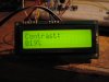
100% is 100% PWM and 0% is 0% PWM, so actually it should say 'PWM' instead of 'Contrast'
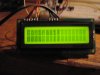
I did some experimenting. Used a 330ohm and 10µF as a lowpass filter. It showed some distortion on higher PWMs. After increasing the capacitor to 100µF the distortion dissapeared. So a capacitor between 10µ and 100µ would be optimal.

 )
)