Electro Tech is an online community (with over 170,000 members) who enjoy talking about and building electronic circuits, projects and gadgets. To participate you need to register. Registration is free. Click here to register now.
Welcome to our site! Electro Tech is an online community (with over 170,000 members) who enjoy talking about and building electronic circuits, projects and gadgets. To participate you need to register. Registration is free. Click here to register now.
For VoH the highest output of the comparator and VoL the lowest output of the comparator...
The trip point high is:
ViH=-VoL*R1/R2
and the trip point low is:
ViL=-VoH*R1/R2
so the total hysteresis is ViH-ViL which is also:
Vhys=VoH*R1/R2-VoL*R1/R2
which of course is also:
Vhys=(VoH-VoL)*R1/R2
Example: R1=100k, R2=200k, VoH=10v, VoL=-10v
ViH comes out to 5 volts and ViL comes out to -5 volts and the difference ViH-ViL is the total
hysteresis which comes out to:
Vhys=5-(-5)=10 volts
We also must enforce a constraint on R2 as:
R2>R1
and notice that this is not R2>=R1 but is actually R2 is greater than R1.
I went over my analysis and have verified that the formulas i had given are indeed correct.
While it is true that we must form the ratio R2/(R1+R2) to calculate the voltage at the
non inverting terminal of the comparator, this is definitely *NOT* the voltage that we need
to solve for in order to determine the operating hysteresis voltage.
In fact, your example of R1=R2 will not even work with a comparator operating from the
same voltage sources as the integrator because the input voltage would need to exceed
the power supply rails to trip the comparator (the only way it would work is if we got
lucky in real life and R2 happened to be just slighly above R1).
I'll repeat the analysis here to prove these results and suggest that if you still have
doubts that you perform a simulation of the circuit and see what happens.
Proof:
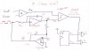
Looking at the circuit we can see that the comparator trips when the non inverting terminal gets
just above or just below zero volts. We'll analyze this action when the input is going higher
and see what we get.
We'll call the highest input before the comparator trips ViH and noting that at this time the output
is at it's lowest which is approximately equal to the minus supply voltage V- which we will call
VoL. Looking at the lower diagram in the attachment we first write the equation for the non
inverting terminal:
(ViH-VoL)*R2/(R1+R2)+VoL=Vnon (the non inverting terminal voltage)
and noting that the point where the comparator trips is just slightly above zero we set Vnon
equal to zero:
(ViH-VoL)*R2/(R1+R2)+VoL=0 (the non inverting terminal voltage will be zero when it trips)
This is our equation for the non inverting terminal which for this circuit is zero when the
comparator trips. Solving this equation for ViH we get:
ViH=-VoL*R1/R2
which is simply -VoL times the ratio R1/R2.
Let's check this using the values shown on the attached diagram and supply voltages of
plus and minus 10 volts...
First calculating ViH using the formula developed above we get:
ViH=-(-10)*100000/200000
which is equal to +5 volts.
Now lets solve more directly using the lower part of the attachment...
With the non inverting terminal at zero volts the current though R2 is:
iR2=(0-(-10))/200000
which comes out to 50uA. Now this same current must flow through R1 and to get the voltage
across R1 we multiply R1 times the current through it:
vR1=100000*0.000050
and of course this is again equal to plus 5 volts, which proves at the very least that
the forumla works when R1=100k and R2=200k. We can prove this also for any values of R1
and R2 to prove that it works with any two values.
A little more analysis also shows that R2 must be restricted to values that are above
the value of R1 or else the circuit wont work at all when the max and min input voltages
are sourced from the same power supply as the output of the comparator (as in this
actual application).
How do I drive the T-flip flop in 2 phase PWM system? Do i use the output of the comparator that has hysteris in it ie. A square wave ?(see diagram in 1st post)
This site uses cookies to help personalise content, tailor your experience and to keep you logged in if you register.
By continuing to use this site, you are consenting to our use of cookies.

") I understand now
I understand now