Continue to Site

Welcome to our site!

Electro Tech is an online community (with over 170,000 members) who enjoy talking about and building electronic circuits, projects and gadgets. To participate you need to register. Registration is free. Click here to register now.

  • Welcome to our site! Electro Tech is an online community (with over 170,000 members) who enjoy talking about and building electronic circuits, projects and gadgets. To participate you need to register. Registration is free. Click here to register now.

Pushwheel Lock help

Status
Not open for further replies.

Electrophile07

New Member
Hey there,
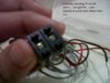
Well I need help with another electronics project guys, the circuit diagram is attached below.
First of all I would like to know what configuration those transistors are in. Im confused between common emitter and common collector.
Secondly, how does the relay even have something to do with the LED, because they are connected to the collectors of different transistors right?
And lastly, correct me if I am wrong, but this is what I have understood.

The pushwheel lock on the left has one code for 'Setting the RS Flip flops' and one code for 'Resetting' them. Here it seems its 86 for opening and 24 for closing. As you can see, when 87 is set on the pushwheel, the output of the wheel goes high giving high inputs to Nand gate N1. So its output is low. Consequently Nand gate n4 will go high and feed the current directly into the base of transitor t1. I cant explain anything after this so please help me out on that.

Side note: theoretically, my push wheel must make the led glow when the rs flip flops are set which is only done when pins 8 and 6 of the respective thumbwheels are high. So my lock opening code should be 86. However this doesnt happen. The circuit works but the lock opens at 97 and closes at 35 (resetting the ff).
So please can someone explain it to me??

Thanks!
 

Attachments

  • cct.png
    cct.png
    18.7 KB · Views: 314
The ten outputs of each of the two ICs on the left are numbered 0 to 9, whereas you are counting 1 to 10.
 
I didn't quite get what you mean.... I connected it exactly as given in the diagram....on the first one Ive connected it to the pin labelled 2 and 8 and on the second one ive connected it to the pin labelled 4 and 6....so these are the decimal equivalents right? (I'm probably making some stupid mistake here ) Ive attached a photo below showing you the soldering to pins common, 4 and 6 on one of the ic
And also please tell me about what configuration those transistors are in....
 

Attachments

  • IMG-20131227-01142.jpg
    IMG-20131227-01142.jpg
    86.4 KB · Views: 282
First of all I would like to know what configuration those transistors are in. Im confused between common emitter and common collector.
They are a variation of a "Darlington" configuration - two transistors connected the give high current gain.
I am not sure that is really necessary here, but the circuit designer thought it was a good idea.

Secondly, how does the relay even have something to do with the LED, because they are connected to the collectors of different transistors right?
When Pin11 of N4 goes high, transistor T1 is turned on, current will flow through LED1, (apart from the fact that as drawn, it is the wrong way round!) causing it to illuminate.
When T1 is on, it will put current into the base of T2, in turn T2 will turn on causing current to flow through the relay, the relay will operate.
So, cutting a long story short, when the LED is illuminated, the relay is energised.

JimB
 
on the first one Ive connected it to the pin labelled 2 and 8 and on the second one ive connected it to the pin labelled 4 and 6....so these are the decimal equivalents right?
Correct. If the thumbwheel pins are wired like that then the lock should open with '86' and close with '24'. Note that the count starts at zero. But although the pins are numbered 0-9, are the wheel rims marked 0-9 or 1-10?
 
Thank you Jim and alec_t......
Alec - The wheel rims are marked 0-9.....I checked them(cant' be marked 1-10 because how can you fit 2 digits on a single rim?) I've attached a picture below.
Is there a faint possibility that this is a manufacturing mistake of some sort? Here's the website **broken link removed**
Unfortunately, I cannot find any specification about the make (other than the company) but my best bet is that it would either be PCS 221E here **broken link removed** or PCS301 **broken link removed**
They havent given the exact same layout as the pin diagram Ive attached in my earlier comment so I guess you'll have to figure that out for me please.....
Anyways,
Thanks again and have a HAPPY NEW YEAR!:)
 

Attachments

  • IMG-20131231-01145.jpg
    IMG-20131231-01145.jpg
    187.3 KB · Views: 274
hi,
Those Decimal thumb push switches are connected internally as follows:
When '0' is selected the Common wiper is in contact with the PCB track marked '0'
When '1' is selected the Common wiper is in contact with the PCB track marked '1'
etc....

EDIT:
I make the circuit diagram as 86 and 24 are the active settings.
You have each wire, wired one position out on the DeciSw PCB
E
 
Status
Not open for further replies.

Latest threads

New Articles From Microcontroller Tips

Back
Top