Continue to Site

Welcome to our site!

Electro Tech is an online community (with over 170,000 members) who enjoy talking about and building electronic circuits, projects and gadgets. To participate you need to register. Registration is free. Click here to register now.

  • Welcome to our site! Electro Tech is an online community (with over 170,000 members) who enjoy talking about and building electronic circuits, projects and gadgets. To participate you need to register. Registration is free. Click here to register now.

Push / Pull solenoid resonator

Status
Not open for further replies.

Spadez

New Member
Hi,

For a project I need two things. First I need to show the power draw with a push / pull solenoid. I think this will be easy to do since I can just use an ammeter and connect the solenoid to a DC supply.

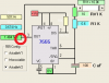
The second thing is I need to move the solenoid in and then out very quickly, say at least 10 times a second. Is there a very simple circuit I could build which will allow me to do this, perhaps without having to program a PIC?

James
 
OK, you have a 12 VDC solenoid. Once you know the current the solenoid coil draws you can think about using a 555 set up as an astable multivibrator to drive it at a free running frequency of about 10 Hz. Then with coil current known the 555 can either drive a transistor, mosfet or whatever to drive the coil. At 10 Hz that solenoid will be slamming along pretty fast and I hope it can mechanically meed the demand. Make sure you place a diode across the solenoid coil (cathode to positive).

Ron
 
Is the "push/pull" solenoid a spring return type on either the push or the pull direction, or do you need to reverse the polarity across the coil to change direction of movement?

Ken
 
Then you need an "H-Bridge" to drive it.
 
After talking to the ebay user it apprears like the auction is a little misleading. It is infact returned by a spring. So it actually works by sinlge polarity, which is returned by the spring. I think this will make the circuit more simple. So really when I need is a circuit which will allow me to pulse 12V.

In an ideal world I would be able to use a variable resistor to vary the frequency as which 12V is pulsed.

Is there a simple circuit using a transistor and 555 timer which will allow me to do this?
 
Last edited:
Ive been looking around, there seems to be lots of tutorials on this.

I guess I need something like this, with a transistor in place of the LED?

The 555 Astable Breadboard Circuit

EDIT: This one looks perfect actually, does it look ok?:

10867-flasher 555.gif
 
Last edited:
On the off chance the solenoid coil current required is low enough (< 150 mA or so) there is a possibility the 555 could directly drive the solenoid. The 555 timer output on pin 3 can source or sink up to 200mA. If the coil current exceeds 200 mA (which is likely) then a transistor is added to drive the solenoid coil. The first step is to know the coil current required. That will determine not only if a transistor is required but what transistor would be the best choice to use. However, yes, that is the basic circuit you want and should do fine.

Ron
 
How can I calculate the flash frequency based on the capacitors and resistors? Ideally I would like to range it from say 1hz to 10hz.

The solenoid is around 300mA so I will need a transistor unfortunately
 
Hi.

I thought an H-bridge was only needed when it was controlled by a reversible polarity. Im not sure how quick it can run, that's why I want to make it adjustable from 1-10Hz so I can see what it can do.
 
After talking to the ebay user it apprears like the auction is a little misleading. It is infact returned by a spring. So it actually works by single polarity, which is returned by the spring. I think this will make the circuit more simple. So really when I need is a circuit which will allow me to pulse 12V.

Unfortunatly I made a mistake, I originally thought it was controlled by reverse polarity.
 
Thank you for the reply, I will download the program now.

I have a few IRL540's laying around at home, I know they may be overkill since since they are logic level driven and are N-channel Mosfet (hexfet) will they be suitable to use?

Also, when you say "across the solenoid coil", does this simply mean from the + terminal to the - terminal of the solenoid?

Yes, diode cathode to to +V and the Anode to the FET Drain

I would recommend that you have decoupling caps on the 555 power lines, say a 100nF and 22uF
 
Last edited:
Just to double check, is it ok to use the IRL540 mosfet?

Also, using your diagram I have worked out the resistors and caps I need. Is it right that the period will be the same for both on and off cycles? Also is it correct that the output is on pin 3 like I have circled in my attachment?
 

Attachments

  • Untitled.png
    Untitled.png
    8.5 KB · Views: 279
Just to double check, is it ok to use the IRL540 mosfet?

Also, using your diagram I have worked out the resistors and caps I need. Is it right that the period will be the same for both on and off cycles? Also is it correct that the output is on pin 3 like I have circled in my attachment?

hi,
Using that configuration for the 555 will give a 1:1 mark/space ratio output on pin 3.
Connect a 470R from pin3 to the Gate of the IRL540.
Operate the 555 from at least a 5Vsupply in order to ensure a satisfactory Vgs turn on voltage, you could use the available 12V for the 555, ensure there is
good decoupling on the 12V line, say a 220uF or higher and a 100nF cap. [1N4001 suppression diode across the solenoid coil]
 
Status
Not open for further replies.

Latest threads

New Articles From Microcontroller Tips

Back
Top