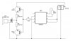
You do not have an amplifier, an amplifier has voltage gain. Yours has emitter-followers so it has no voltage gain. Since the transistors are not biased then the p-p output is 1.4V LESS than the input. The useless 2.2 ohm resistors also reduce the output level.
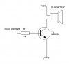
The datasheet of the toy sound generator does not show its output level since it is designed to drive ONE COMMON-EMITTER TRANSISTOR that you do not have. A common-emitter transistor has a lot of voltage gain (your circuit has voltage loss, not voltage gain).
If the output from the IC is 1V p-p then your transistors do nothing.
If the output from the IC is 1.6V p-p then the output of your transistors is 0.2V p-p which is almost nothing.
Your 12V supply is not being used since the output from your transistors is so low.
There are THOUSANDS of audio amplifier schematics in Google. Use one.