Hi!
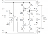
Im still newbie to this analog circuit design, so i have something to ask about the circuit in the attachment below. The circuit is Push Pull Class B Amplifier with AB Characteristic.
My questions are:
1)The purpose of mirror currents is to provide a current into to the collector of T5,right? For what purpose is it actually and how could i calculate the value of the current at the collector of T5? T7 and T8 are actually diode-connected Transistors, which have a role to eliminate the crossover distortion,right?
2)If the crossover distortion can be eliminated with the T7 & T8, what is the purpose of the negative feedback connection from Vout to the OP, if the switch in opposite direction from the one in the circuit. ( I assume that the feedback can eliminate the crossover distortion too)
3) How could i calculate the gain of the OP exactly?
4) Both Re1 and Re2 could reduce the power dissipation at the T1 and T2 right?
Thanks!!
Sorry for many questions, i have read a a lot and need some confirmation and guidance about this circuit.