PWKseeker_127eq
New Member
Good day, can anyone help me in this simulation of mine?
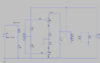
I need to simulate a push-pull amplifier.
In the first part, a dc operating condition:
I need to simulate the terminal voltages of transistors at dc supply VCC voltage such as:
VB1, VE1, VC1, VB2, VE2, and VC2.
The second part is running it in AC operation. Moreover, I need to be able to display 2 cycles of input signal.
And adjust the amplitude of the input sine wave voltage and rerun the transient simulation until the output voltage across the load resistor R8 becomes undistorted.
Also, I need to obtain the waveform of Vin, Vo(undistorted) .
Can anyone help me with this? I've been racking my brain for a several hours now and I can't get my desired output.
Advance Thanks for the feedback.