Hi,
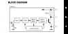
I made circuit from this schematic in attachment that turns on and of appliances using IR receiver TSOP1738 and CD4017. When there is a IR signal from TV remote (or other source),
TSOP1738 will output 0 V, so PNP transistor will be on, so the signal will go to the CD4017 and output 1 (pin 2) will be enabled (turn on). This CD4017 turns on next output based on rising edge on clock pin (pin 14). Because output 2 (pin 4) is connected to reset (pin 15), when we press TV button second time, there will be HIGH signal to output 2 and therefore to reset, so CD4017 will start from beginning once again. I know that capacitor C1 (100uF) is to prevent multiple pulses from TV remote going to CD4017 (because TV remote output several pulses) that will turn on and off appliance multiple times. But, what is the purpose of capacitor C2 (0.1uF)?
Attachments
Last edited: